The fuel strainer, which is
s. .
'2 %(
-
.1
•
ti
N
.
•
a
SECTION II
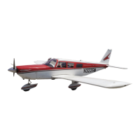
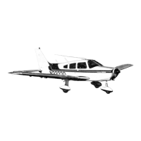
THE PIPER CHEROKEE
•
THE PIPER CHEROKEE
SECTION,
reserve quantity of 50
gallons the tanks are filled
completely to the top. This
system allows the fuel
quantity to be varied con-
veniently according to the
payload.
An auxiliary electric
fuel pump is provided for
use in case of failure of the
engine driven pump. The
electric pump should be on
for all take-offs and landings.
equipped with a quick drain, is
located on the front lower left corner of the firewall. This
strainer should be drained regularly to check for water or
sediment accumulation. To drain the lines from the tanks, the
tank selector valve must be switched to each tank in turn, with
the electric pump on, and the gascolator drain valve opened.
Each tank has an individual quick drain located at the bottom,
inboard, rear corner.
Fuel quantity and pressure are indicated on gauges located
in the engine gauge cluster on the right side of the instrument
panel.
ELECTRICAL SYSTEM
The electrical system in-
cludes a 12 volt alternator,
battery, voltage regulator
and master switch relay.
The battery, regulator and
relay are mounted in the
battery compartment immed-
iately aft of the baggage com-
partment. Access for service
or inspection is conveniently
obtained through a removable
panel at lower right corner of the compartment.
Electrical switches, fuses and fuse spares are located
on the lower left center of the instrument panel, and the left
side of the instrument sub-panel.
Standard electrical accessories include: Starter, Electric
Fuel pump, Fuel Gauge, Stall WarningInclicator, Cigar Lighter
and Ammeter.
Navigation Lights, Anti-Collision Light, Landing Light,
Instrument Lighting and the Cabin Dome Light are offered as
optional accessories.
Circuit provisions are made to handle optional commun-
ications and navigational equipment.
Installed on the Cherokees is the F.T.P. (full time power)
electrical system.
Derived from the system are many advantages both in
operation and maintenance. The main advantage is, of course,
full electrical power output regardless of engine R. P.M. This
is a great improvement for radio and electrical equipment
operation. Also because of the availability of generator out-
put at all times, the battery will be charging for a greater
percentage of use, which will greatly improve cold-morning
starting.
Unlike previous generator systems, the ammeter does not
indicate battery discharge; rather it displays .in amperes the
load placed on the alternator. With all electrical equipment off
(except the master switch) the ammeter will be indicating the
amount of charging current demanded by the battery. As each
item of electrical equipment is turned on, the current will in-
crease to a totalappearing on the ammeter. This total includes
the battery. The maximum continuous load for night flight, with
radios on, is about 30 amperes. This 30 ampere value, plus
approximately two amperes for a fully charged battery, will
appear
*
continuously under these flight conditions. The amount
of current shown on the ammeter will tell immediately whether
the alternator system is operating normally, as the amount of
current shown should equal the total amount of amperes being
drawn by the equipment which is operating.
If no output is indicated on the ammeter during flight, re-
8
650901
680401
9
 Loading...
