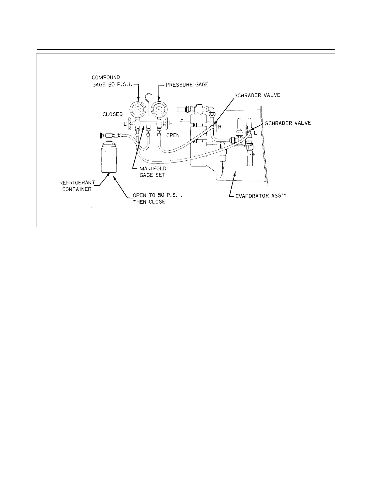
Figure 21-8. Leak Test Hookup
LEAK CHECK - METHOD I.
1. Connect the manifold gauge set into the system and determine if there is any refrigerant in the system.
A minimum of 50 psi refrigerant pressure in the system is needed for leak detection. (Refer to Figure 21-8.)
2. P u rge the hoses of air by allowing some refrigerant to escape from the connections at the service
valves. Then tighten connections at the service valve.
3. Close the low side manifold valve and open the high side manifold valve.
4. Open the refrigerant container service valve and allow the pressure at the low side gauge to reach 50
psi at which time close the high side manifold valve.
5. Close the refrigerant container service valve and remove the hose if no leaks are evident.
6. It is advisable to use an electronic leak detector to check this system instead of an open flame leak
detector due to the possible presence of gasoline fumes in the engine area.
7. If any leaks are found, purge the system of refrigerant, make the necessary repairs and check the
compressor oil.
8. Add oil, if required (refer to Check Compressor Oil and Chart 2105) then repeat Steps 1 through 5.
9. If no further leaks are found, the system may be evacuated and charged. (Refer to Evacuating the
System and Charging the System.)
21-50-08
Page 21-20
December 1, 1978
1F19
PIPER AIRCRAFT
PA-28RT-201 / 201T
MAINTENANCE MANUAL
 Loading...


