X P 1 M I N S T A L L E R G U I D E
10
Normal precautions to avoid possible causes of harmful interference
should be employed… e.g. avoid running with heavy duty mains cables
or adjacent to fluorescent lighting etc.
A maximum of 16 door controllers (XP1Ms PLAN200s or
PLAN400s) can be connected to any single comms port.
Care should be employed when using twisted pair cables that include
multiple ‘black’ conductors. ‘Crossing’ the black conductors between
panels will cause spurious faults that may be difficult to track down.
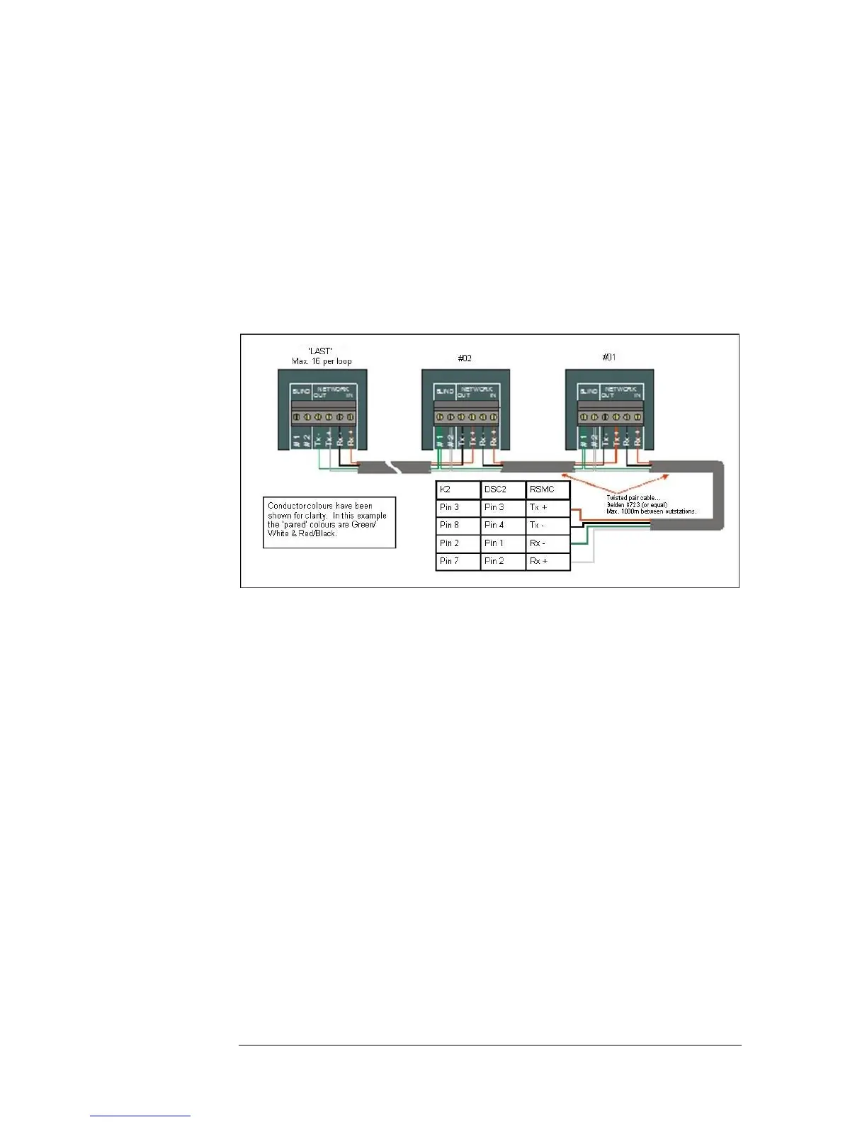
P L A N N E T W O R K C O N N E C T I O N D I A G R A M
Note above that the ‘BLIND’ terminals have been used to link the ‘through’
pair in the IN and OUT cables. These termination points have no connection
to the panel electronics and are provided solely for the purpose of linking the
‘straight-through’ pairs. The Blind terminals are not used in controllers situated
at the end of a chain.