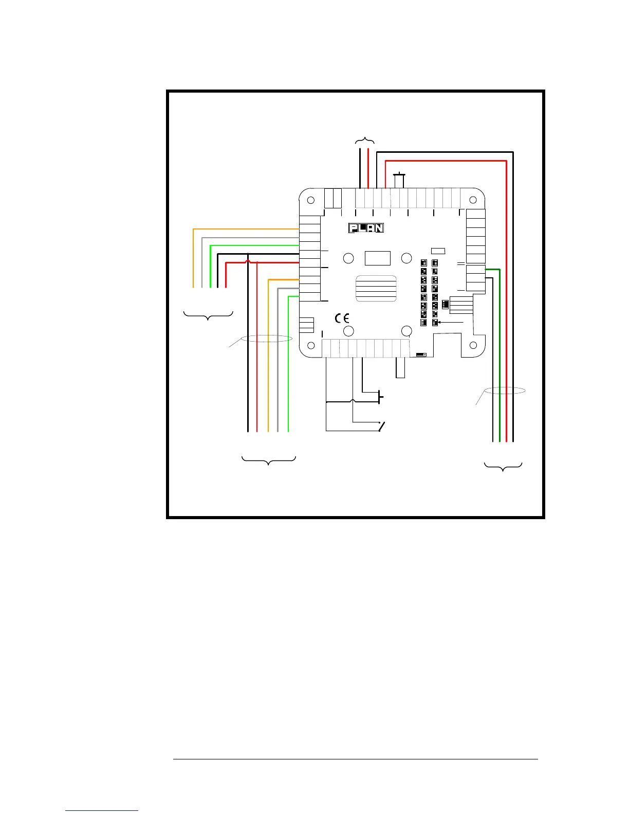
Door Egress Switch (DR input)
As can be seen in the diagram above, an input (DR) is provided on each reader
port for a normally open ‘momentary operation’ egress switch. Whenever the
DR (Door Release) input is pulsed low (via the RTE switch) the lock output
will be switched for the pre-selected lock delay time.
The RTE is generally used in the following circumstances…
to provide an exit signal in the case of alarmed doors.
to allow a means of exit for doors with no mechanical override (e.g.
Mag-locks).
to allow the location of a remote override button.