- 1 -
- 2 -
- 3 -
- 4 -
- 5 -
- 6 -
- 7 -
- 8 -
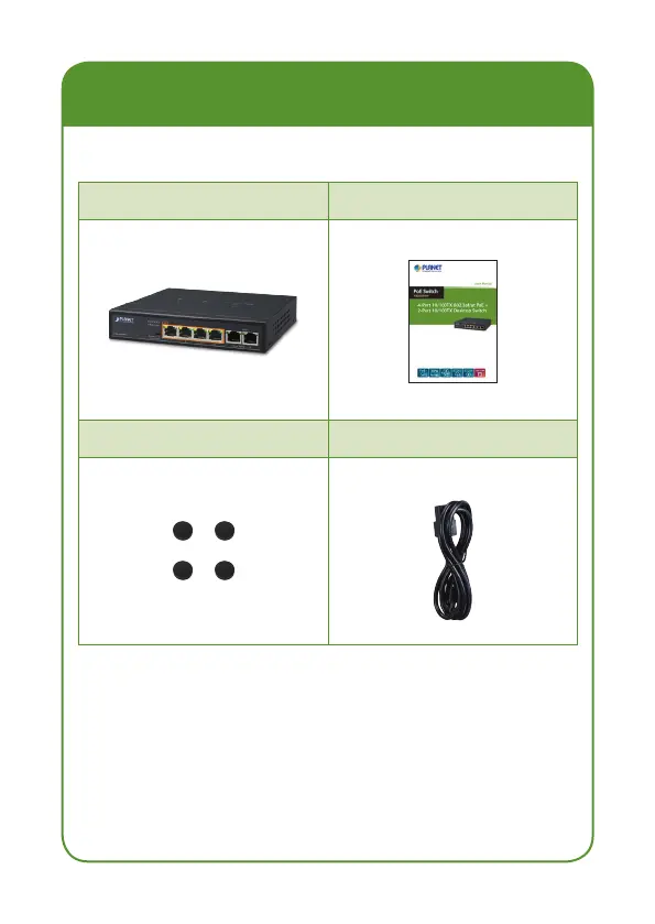
1. Package Contents
Check the following contents of your package:
FSD-604HP User’s Manual
Foot Pad Power Cord
If any of these are missing or damaged, please contact
your dealer immediately; if possible, retain the carton
including the original packing material, and use them
again to repack the product in case there is a need to
return it to us for repair.
Extend PoE Mode
Standard PoE Mode
Power
PoE IP Camera
PoE
10BASE-T UTP with PoE
PoE
100BASE-TX UTP with PoE
PoE
100 meters (328 feet)
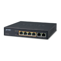
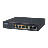
FSD-604HP
FSD-604HP
Power
PoE
250 meters (820 feet)
PoE IP Camera
Note
After changing the mode, you need to
manually restart the FSD-604HP to make
the corresponding configuration take effect.
2. Product Features
RJ45 Interface
6-port 10/100TX Ethernet RJ45 copper
4-port IEEE 802.3at/af PoE Injector (Port-1 to
Port-4)
Power over Ethernet
Complies with IEEE 802.3af/at Power over Ethernet
end-span PSE
Up to 4 IEEE 802.3af/2 IEEE 802.3at devices
powered
Supports PoE power up to 30 watts for each PoE
port
60-watt PoE budget
Hardware DIP switch for “Standard” and “Extend”
mode selection; the “Extend” mode features
30-watt PoE transmit distance of 250m at speed of
10Mbps and VLAN isolation
Auto detects powered device (PD)
Circuit protection prevents power interference
between ports
Remote power feeding up to 100m in standard
mode
Switching
Hardware-based 10/100Mbps auto-negotiation and
auto MDI/MDI-X
Flow control for full duplex operation and back
pressure for half duplex operation
1536bytes packet size
Integrates address look-up engine, supporting 2K
absolute MAC addresses
Automatic address learning and address aging
Solid DIP switch to isolate ports to prevent
broadcast storm and defend DHCP spoong
Hardware
Desktop palm size
LED indicators for PoE ready/activity and LINK/ACT
Supports Contact Discharge of ±4KV DC and Air
Discharge of ±6KV DC for Ethernet ESD protection
Supports ±4KV Surge Immunity
Internal AC power supply
Fanless design
4. LED Indicators
System
LED Color Function
PWR Orange
Lights to indicate the Switch has
power.
Per 10/100Mbps Port
LED Color Function
PoE Orange
Lights to indicate the port is
providing 52V DC in-line
power to remote PoE PD.
LNK/ACT Green
Lights to indicate the link through
that port is successfully
established at 10/100Mbps.
Blinks to indicate that the Switch
is actively sending or
receiving data over that
port.
3. Switch Front Panel
Figure 3-1 shows the front panel of the FSD-604HP.
PoE
1 2 3 4
5 Uplink 6
ACTLNK
PoE In-use
FSD-604HP
PWR
Standard
Extend
Figure 3-1: FSD-604HP Front Panel
The front panel of the FSD-604HP provides one DIP
switch for “Standard” and “Extend” mode selections.
The detailed descriptions are shown in the following
table.
DIP Switch
Mode
Function
Standard
(default)
This mode makes the FSD-604HP operate
as a general switch and all ports operate
at 10/100Mbps auto-negotiation.
Extend
This mode makes the FSD-604HP
operate as a VLAN isolation switch and
port 1 to port 4 will isolate respectively.
Port 1 to port 4 can communicate with
port 5~6 (uplink port).
This mode also makes the FSD-604HP
operate at auto–negotiation 10Mbps
speed duplex mode only, but the
delivery distance of PoE power and
network data can reach 250m.
5. Switch Rear Panel
Figure 5-1 shows the rear panel of the FSD-604HP.
100~240V AC 50/60Hz
Figure 5-1: FSD-604HP Rear Panel
Power
Notice
1. The device is a power-required device,
meaning it will not work till it is pow-
ered. If your networks should be active
all the time, please consider using UPS
(Uninterrupted Power Supply) for your
device. It will prevent you from network
data loss or network downtime.
2. In some areas, installing a surge sup-
pression device may also help to protect
your FSD-604HP from being damaged by
unregulated surge or current to the FSD-
604HP.
6. Installing the Switch
This part describes how to install your FSD-604HP and
make connections to it. Please read the following topics
and follow the procedures as presented.
Note
This FSD-604HP does not need software
configuration.
Desktop Installation
To install the FSD-604HP on desktop, simply follow the
following steps:
Step 1: Place the FSD-604HP on desktop near an
electrical outlet.
Step 2: Keep enough ventilation space between the
FSD-604HP and the surrounding objects.
Note
When choosing a location, please keep in
mind the environmental restrictions dis-
cussed in Chapter 7 -- Product Specifica-
tions.
Step 3: Connect your FSD-504HP to network devices.
A. Connect one end of a standard network
cable to the Port-5~6 of the FSD-604HP
that marks with “Uplink”.
 Loading...