10
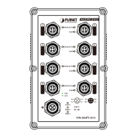
3.3 Switch Upper Panel
The upper panel of the Industrial Ethernet Switch consists of one terminal
block connector within two power input and one relay ouput.
V1+ V1- V2+ V2-
PWR1
PWR2Alarm
DC Input: 12-48V
, 2A max.
AC Input: 24V
, 1A max.
Max. Fault Alarm Loading: 24V, 1A
1 2 3 4 5 6
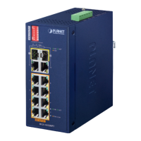
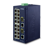
Figure 2: IFGS-1822TF Top View
3.4 Wiring the Power Inputs
The 6-contact terminal block connector on the top panel of Industrial Ethernet
Switch is used for two redundant power inputs. Please follow the steps below
to insert the power wire.
When performing any of the procedures like inserting the wires
or tightening the wire-clamp screws, make sure the power is
OFF to prevent from getting an electric shock.
1. Insert positive and negative DC power wires into contacts 1 and 2 for
POWER 1, or contacts 5 and 6 for POWER 2.
V1+ V1- V2+ V2-
PWR1
PWR2Alarm
DC Input: 12-48V
, 2A max.
AC Input: 24V
, 1A max.
Max. Fault Alarm Loading: 24V, 1A
1 2 3 4 5 6
 Loading...