10
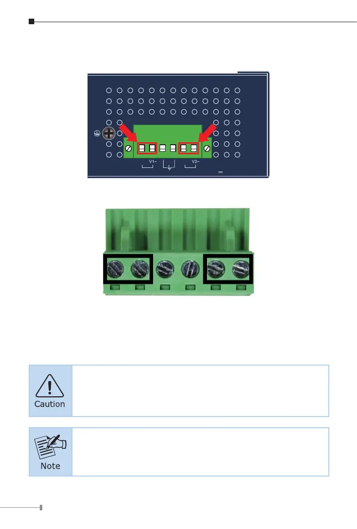
1. Insert positive and negative DC power wires into contacts 1 and 2 for
POWER 1, or contacts 5 and 6 for POWER 2.
Max. Fault Alarm Loading: 24V, 1A
V1+
V2+
PWR1
PWR2Alarm
DC Input:
12-54V , 6A max.
1 2 3 4 5 6
2. Tighten the wire-clamp screws for preventing the wires from loosening.
1 2 3 4 5 6
V1+ V1- V2+ V2-
Power 1 Alarm Power 2
Figure 5: PWR1 & PWR2 pins of terminal block.
PWR1 and PWR2 must provide the same DC voltage while
operating with dual power input.
The wire gauge for the terminal block should be in the range
between 12 and 24 AWG.