9
TO PREVENT THE DEVICES FROM DAMAGE, please make sure
the remote devices support either the Legacy or Force Mode
before turning the DIP switch to the Legacy Mode.
Adjust the DIP switch to the desired mode before powering on
the IPOE-470 series.
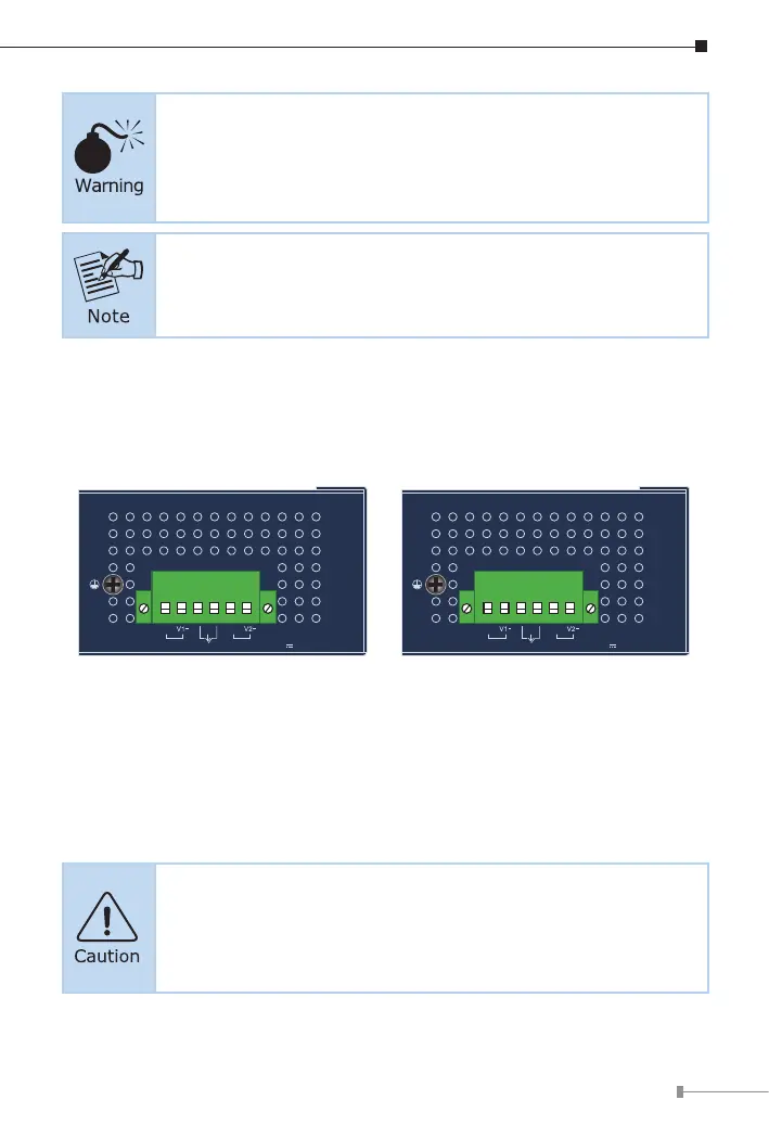
3.3 Device Top Panel
The upper panels of the Industrial PoE++ Injector Hubs consist of one terminal
block connector within two power inputs.
Max. Fault Alarm Loading: 24V, 1A
V1+
V2+
PWR1
PWR2Alarm
DC Input:
48-54V , 5A max.
1 2 3 4 5 6
Max. Fault Alarm Loading: 24V, 1A
V1+
V2+
PWR1
PWR2Alarm
DC Input:
12-54V , 6A max.
1 2 3 4 5 6
Figure 3: IPOE-470 Top View Figure 4: IPOE-470-12V Top View
3.4 Wiring the Power Inputs
The terminal block connector on the top panel of Industrial PoE++ Injector
Hub is used for two DC redundant power inputs. Please follow the steps below
to insert the power wire.
When performing any of the procedures like inserting the wires
or tightening the wire-clamp screws, make sure the power is
OFF to prevent from getting an electric shock.