6
3. Hardware Introduction
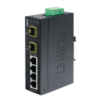
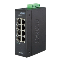
3.1 Three-View Diagram
The three-view diagram of the Industrial Ethernet Switch consists of ve or
eight auto-sensing 10/100BASE-TX RJ45 port and one removable 6-pin terminal
block. The LED indicators are also located on the front panel.
104.00
30.00
70.00
18.00
9.00
91.00
52.00 52.00
50.00
30.00
28.00
48.80 40.00
18.00
40.00
18.00
147.00
Mounting Kit
Mounting Kit
DIN-Rail Kit
Unit: mm
Rear ViewSide View Side View
Top View
Front View
Bottom View
P1 P2 Fault
ACT
LNK
10/100
1
2
3
4
5
ISW-500T
Max. Fault Alarm Loading: 24V, 1A
DC Input: 12-48V
, 0.17A max.
AC Input: 24V
, 0.15A max.
Alar m
V1+ V2+
PWR2PWR1
Figure 1: ISW-500T Three-View Diagram
 Loading...