14
z Band Plan
t User can switch the Band Plan either Symmetric or Asymmetric
by their own. When Symmetric is selected, it provides better
upstream performance. When Asymmetric is selected, it provides
better downstream performance. Please refer to the above table
for details.
z Target SNR (Signal Noise Ratio) Margin
t When xed SNR margin is selected, the system will maintain the
SNR margin at 9 dB across all usable loop length.
Note
By default setting, DIP 4 switch is set at “ON” position
and operate as “Slave”. To operate as “Master”, please
set DIP 1 switch to “OFF” position. Adjust other DIP
switch settings according to different network application
demands
Please power off the PoE Industrial Ethernet Extender before making
any transmission mode adjustment.
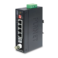
2.2 The Upper Panel
The upper panel of the PoE Industrial Ethernet Extender consists of one
terminal block connector within two DC power inputs.
Figure 2-2 shows the upper panel of the PoE Industrial Ethernet
Extender.
Input
DC 24V / 48V
V1- V1+ V2- V2+
PWR1
PWR2Fault
Figure 2-2 PoE Industrial Ethernet Extender Upper Panel.