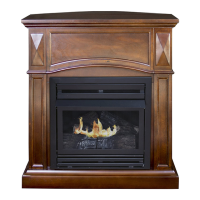
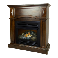
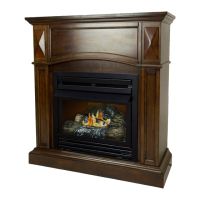
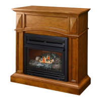
EasyManua.ls Logo

pleasant hearth VFF-PH32DR - User Manual

pleasant hearth VFF-PH32DR
84 pages
Print Icon
To Next Page IconTo Next Page
Loading...
1
VENT-FREE GAS
DUAL FUEL FIREPLACE
MODEL #VFF-PH(20D)(20DB)(20D-C)(CPD-2T)
VFF-PH(26D)(26D-T)(IMD-2H)
VFF-PH(32DR)(32DR-H)(FSDR-2C)
INSTALLER: Leave this manual with the appliance.
CONSUMER: Retain this manual for future reference.
WARNING: IF THE INFORMATION IN THIS MANUAL IS NOT FOLLOWED
EXACTLY, A FIRE OR EXPLOSION MAY RESULT CAUSING PROPERTY
DAMAGE, PERSONAL INJURY OR LOSS OF LIFE.
CAUTION - FOR YOUR SAFETY
Questions, problems, missing parts? Before returning to your retailer, call our customer
service department at 1-877-447-4768, 8:30 a.m. – 4:30 p.m., CST, Monday – Friday or
email us at customerservice@ghpgroupinc.com.
WARNING: This appliance
is equipped for (Natural and
Propane) gas. Field conversion
is not permitted other than
between natural or propane
gases.
- Do not store or use gasoline or other ammable vapors and Iiquids in vicinity of this or
any other appliance.
WHAT TO DO IF YOU SMELL GAS
• Do not try to light any appliance.
• Do not touch any electrical switch; do not use any phone in your building.
• Immediately call your gas supplier from a neighbor’s phone. Follow the gas supplier’s
instructions.
• If you cannot reach your gas supplier, call the re department.
- Installation and service must be performed by a qualied installer, service agency or the
gas supplier.
This is an unvented gas-red heater. It uses air (oxygen) from the room in which it is
installed. Provisions for adequate combustion and ventilation air most be provided.
Refer to Air For Combustion and Ventilation section on page 9-11 of this manual.
This appliance may be installed in an aftermarket, permanently located manufactured (mobile)
home, where not prohibited by local codes. This appliance is only for use with propane or
natural gas. This appliance is equipped with a simple means to switch between propane and
natural gas. Field conversion by any other means including the use of a kit is not permitted.
NG
LP
Dual Fuel
0418GF006S
ANSI Z21.11.2-2013
IMDFVFF - 2015-09-16

Other manuals for pleasant hearth VFF-PH32DR

Questions and Answers

Summary

Important Safety Information

General Safety Precautions

General warnings for safe operation, handling, and clearances.

Carbon Monoxide and Gas Safety

Information on CO poisoning symptoms, gas leaks, and odor.

Clearance and Placement Warnings

Maintain clearances from combustibles and traffic areas.

California Proposition 65

Information on chemicals in fuels and combustion products.

Safety Information

Appliance Fuel and Operation Restrictions

Appliance fuel type, tank placement, prohibited locations, and log usage.

Ventilation and ODS System

Heater needs fresh air; ODS shuts off if insufficient air is available.

Maintenance and High Altitude Operation

Servicing requirements, effects of high altitude, and clearances.

Qualified Installing Agency

Requirement for qualified personnel for installation and servicing.

Product Identification

Fireplace Model Identification

Diagrams showing components of different fireplace models.

Mantel Cabinet Installation Note

Fireplace installed in mantel cabinet; using other mantels voids warranty.

Product Features

Safety Pilot System (ODS)

Oxygen Depletion Sensing (ODS) shuts off heater if fresh air is insufficient.

Electric Push Button Ignition

Electronic piezo control system requiring one AAA battery.

Thermostat Heat Control

Automatically cycles burner to maintain desired room temperature.

Dual Fuel Capability

Operates on propane or natural gas; factory set for propane.

Optional Blower Kit

Blower kit distributes warmed air more rapidly.

Massachusetts State Requirements

Specific installation and appliance requirements for Massachusetts.

Local Codes and Standards

Follow local codes; use National Fuel Gas Code, ANSI Z223.1/NFPA 54 if none exist.

Unpacking Instructions

Hood Assembly

Screen Installation Warning

Always have screen in place before operating fireplace.

Parts Positioning Warning

Failure to position parts correctly may cause damage or injury.

Tools Required for Assembly

Phillips screwdriver and scissors are needed.

Screen Removal and Hood Installation

Steps for removing the screen and attaching the hood.

Preparing for Installation

Air for Combustion and Ventilation Warning

Heater requires adequate indoor combustion air per codes.

Producing Adequate Ventilation

Classifies spaces into Unusually Tight, Unconfined, or Confined Construction.

Confined and Unconfined Space Definitions

Defines confined and unconfined spaces based on volume per BTU/hr.

Unusually Tight Construction Details

Criteria for unusually tight construction and need for additional fresh air.

Determining Fresh-Air Flow for Heater Location

Worksheet to determine if space is confined or unconfined.

Calculating Space Volume and BTU Support

Steps to calculate space volume and maximum BTU/hr the space can support.

Adding BTU;hr of Appliances

Sum all fuel burning appliances' BTU/hr in the space.

Confined vs. Unconfined Space Determination

Compare space support vs. appliance BTU/hr to determine space type.

Options for Additional Fresh Air

Options include reworking worksheet, venting outdoors, or using lower BTU heater.

Ventilation Air From Inside Building

Providing ventilation from adjoining unconfined space via openings or doors.

Ventilation Air From Outdoors

Providing ventilation from outdoors using grills or ducts.

Attic Ventilation Warning

Do not provide openings to attic if it has a thermostat-controlled power vent.

Installation

Fuel Selection Means Warning

Do not attempt to change fuel selection means; must be done by qualified person.

Supplemental Heat Notice

Heater intended for supplemental heat; use with primary heating system.

Qualified Technician Requirement

A qualified technician must install the heater and follow local codes.

Prohibited Installation Locations

Never install in bedroom, bathroom, RV, near flammables, high traffic, or drafty areas.

Clearance Requirements Warning

Maintain minimum clearances, provide greater if possible.

Wall Discoloration Caution

Warm air currents can discolor walls; avoid impurities in air.

Moisture and Mildew Warning

Vent-free heaters add moisture; poor ventilation may cause mildew.

Check Gas Type

Ensure gas supply is correct for your heater.

Clearances to Combustibles

Follow instructions for clearances to combustibles, sit on mantel base.

Fireplace Clearances

Minimum clearances to combustible material, side walls, and ceiling.

Garage Installation Caution

Pilot/burner must be 18" above floor; locate away from moving vehicles in garages.

Convenience and Efficiency Placement

Locate for easy access, in coldest part of room.

Carpet;Combustible Material Installation

Install on metal or wood panel if placed directly on carpeting.

Optional Blower Kit Installation

Follow provided instructions for blower installation and power source.

Mantel Provided Warning

Firebox is for use only with the provided mantel.

Blower Installation Warning (Optional)

Blower plug must be grounded; disconnect gas supply before installing fan.

Mounting Blower (B) to Fireplace Top

Steps for mounting the blower using screws.

Attaching Power Cord (A)

Connect power cord to blower access panel.

Attaching Temperature Sensor (C)

Connect temperature sensor to the combustion top.

Inserting Wires into Line Slot

Insert AUTO, OFF, MAN wires into the line slot on the right corner.

Connecting Wires to Temperature Sensor

Connect female plugs to male ports on the temperature sensor.

Connecting White Power Supply Wire

Insert female plug of white power supply wire to its male port.

Connecting Black Power Supply Wire

Insert female plug of black power supply wire to its male port.

Inserting Blower Link

Insert the blower link (male plug) into the power link (female port).

Securing Wires with Cable Ties

Bind wires with cable ties and attach to holes on back of outer casing.

Inserting AUTO, OFF, MAN Wires

Insert wires through the rocker switch opening.

Connecting Wires to Rocker Switch

Match AUTO, OFF, MAN wires to corresponding ports on rocker switch.

Pushing Rocker Switch into Control Panel

Secure the rocker switch into the control panel.

Reattaching Blower Access Panel

Check wire security and reattach blower access panel.

Electrical Wiring Diagram

Diagram showing electrical connections for the blower system.

Wire Replacement Note

If replacing wire, use wire of equal or greater temperature rating.

Wiring Error Caution

Label wires before disconnecting; wiring errors can cause dangerous operation.

Gas Selection Instructions Warning

Appliance is factory set for propane; do not adjust while operating.

Gas Selection Adjustment Caution

Do not access or adjust gas selection means while appliance is in operation.

Convert to Natural Gas: Regulator Conversion

Steps to convert the pressure regulator for natural gas use.

Convert to Natural Gas: Selector Valve Adjustment

Steps to adjust the gas selector valve for natural gas.

Connecting to Gas Supply Warning

Qualified technician must connect to gas supply; use external regulator.

External Regulator Requirements

Use external regulator for propane/natural gas, adjust pressure as specified.

Private Gas Well Warning

Never connect heater to private (non-utility) gas wells.

Gas Connection Diagram

Diagram showing gas connection with shutoff valve, sediment trap.

Pipe Material Caution

Use new black iron or steel pipe; 1/2 in. diameter or greater.

Shutoff Valve Installation

Install equipment shutoff valve in accessible location; use pipe joint sealant.

Pipe Joint Sealant Caution

Use sealant resistant to gas; install sediment trap in supply line.

Regulator Damage Caution

Hold gas regulator with wrench when connecting fittings.

Installation Items Needed (Not Provided)

List of tools and materials required for installation.

Gas Connection Lines Routing

Options for routing gas connection lines; check local codes for concealed connections.

Flexible Gas Line Installation

Install gas line to fitting and attach to shut off valve.

Checking for Gas Leaks

Check all connections for gas leaks.

Checking Gas Connections Warning

Test all gas piping and connections for leaks; correct leaks immediately.

Open Flame Leak Test Warning

Never use open flame; use soap and water mixture.

Pressure Testing Gas Supply (Excess 1;2 PSIG)

Procedure for testing supply piping at pressures over 1/2 PSIG.

Pressure Testing Gas Supply (Equal to or Less Than 1;2 PSIG)

Procedure for testing supply piping at pressures up to 1/2 PSIG.

Pressure Testing Heater Gas Connections

Steps to test gas connections from shutoff valve to control valve.

Equipment Shutoff Valve Diagram

Diagram illustrating the equipment shutoff valve operation.

Checking Gas Joints Diagrams

Diagrams for checking gas joints for propane/LP and natural gas.

Assembling Logs

Log Assembly Warning

Failure to position parts correctly may cause damage or injury.

Soot Prevention Warning

Check for yellow flames contacting logs; reposition logs if necessary.

Log Identification and Installation

Instructions for installing logs 1 through 5, marked with numbers.

Log Assembly Warning

Failure to position parts correctly may cause damage or injury.

Soot Prevention Warning

Check for yellow flames contacting logs; reposition logs if necessary.

Log Identification and Installation

Instructions for installing logs 1 through 5, marked with numbers.

Decorative Cinders Note

Add decorative cinders around grate base, not on logs or burner.

Operation

Safety Before Lighting

Crucial safety warnings before attempting to light the pilot.

Procedure If Gas is Smelled

Immediate actions to take if a gas odor is detected.

Hand Operation Warning

Use hand only to push/turn gas control knob; never use tools.

Water Damage Appliance Warning

Do not use appliance if any part has been under water.

Lighting Instructions

Step-by-step guide for lighting the pilot and main burner.

Lighting Instructions (Specific Model)

Steps for lighting the pilot and main burner for VFF-PH(32DR) models.

Receiver Switch Setting

Set receiver switch to 'ON' or 'REMOTE' position.

Remote Control Operation (ON;THERMO)

Using the remote to turn the appliance ON or into THERMO mode.

Turning Off Gas to Appliance

Procedure for turning off the gas supply to the appliance.

Remote Control Operation

Transmitter Overview

Diagram and description of transmitter buttons and functions.

Key Settings Explanation

Explanation of ON, OFF, MODE, and SET button functions.

LCD Display Explanation

Explanation of LCD screen indicators: Display, °F/°C, Flame, Room, Temp, Set.

Setting °F; °C Scale

How to change the temperature scale between Fahrenheit and Celsius.

Manual Function Operation

Operating the system in manual mode (ON/OFF).

Thermostat Function Operation

Setting desired room temperature in THERMO mode.

Changing the Set Temperature

How to adjust the desired temperature using the SET key.

Operational Notes

Information on swing/temperature differential and manual function response.

Power Setting

Remote control system powering capability for DC-powered components.

Remote Receiver Placement

Important note on receiver positioning to avoid high temperatures.

Remote Receiver Functions

Operating modes (REMOTE, ON, OFF) and safety lock-out function.

Installation Instructions Warning

Warning against connecting receiver directly to 110-120VAC power.

Installation Location

Mount receiver on or near fireplace hearth, away from extreme heat.

Wiring Instructions

Connecting receiver to solenoid valve using 18 gauge stranded wires.

General Information: Communication Safety

Safety feature for when transmitter is out of range, warning beeps.

CP (Childproof) Feature

Childproof lock-out feature to prevent transmitter operation.

Setting Lock-Out (CP)

How to activate and disengage the childproof lock-out feature.

Learning Transmitter to Receiver

Procedure to pair transmitter security code with the receiver.

Transmitter Wall Clip Installation

Instructions for installing the transmitter wall clip.

Battery Life Expectations

Battery life for transmitter and receiver, recommendations for alkaline batteries.

Troubleshooting Remote System

Steps to troubleshoot problems with the remote system.

Operation

Inspecting Burners

Check pilot flame pattern and burner flame patterns regularly.

Pilot Flame Pattern

Correct and incorrect pilot flame patterns and their implications.

Warning: Yellow Tipping

Yellow tipping may increase CO levels; follow instructions.

Warning: Fan Drafts

Do not allow fans to blow directly into fireplace or create drafts.

Warning: Approved Accessories

Do not use unapproved blower inserts or accessories.

Note: Orange Flames vs. Yellow Tipping

Distinguish orange flames from yellow tipping; dirt can cause brief orange patches.

Care and Maintenance

Burner Flame Pattern

Correct and incorrect burner flame patterns, log curing.

Warning: Turn Off Heater

Turn off heater and let cool before servicing.

Caution: Cleaning Areas

Keep control areas, burner, and air passageways clean; annual inspection recommended.

Warning: Primary Air Opening

Failure to keep primary air openings clean may result in sooting.

Burner Orifice and Pilot Air Inlet

Cleaning primary air inlet holes for proper air mix and clean flame.

Cleaning Procedure Steps

Steps for cleaning burner, pilot assembly, and air inlet holes.

Primary Air Inlet Slot Diagram

Diagram showing primary air inlet slot on burner tube.

Pilot Inlet Air Hole Diagrams

Diagrams showing pilot inlet air holes for LP and NG gas.

LOG SET Care

Refer to log placement instructions; replace if broken or chipped.

CABINET Air Passageways Cleaning

Use vacuum cleaner or pressurized air to clean air passageways.

Exterior Cabinet Cleaning

Wipe exterior cabinet with a soft cloth and mild soap/water mixture.

Troubleshooting

WARNING: If You Smell Gas

Critical steps to take if a gas odor is detected.

IMPORTANT: Heater Odors

Impurities in air can create odors; ventilate and stop using odor-causing products.

WARNING: Power Off Before Servicing

Ensure power is turned off before proceeding with troubleshooting.

WARNING: Cool Before Servicing

Turn off and let cool before servicing; only qualified personnel.

CAUTION: Cleaning ODS;Pilot

Never use wire or needle to clean ODS/pilot; this can cause damage.

SERVICE HINTS: When Gas Pressure Is Too Low

Symptoms and causes of low gas pressure.

Ignitor Button Issues (No Spark)

Troubleshooting for no spark at ODS/pilot when ignitor button is pressed.

Ignitor Button Issues (Spark, No Ignition)

Troubleshooting for spark but no ignition at ODS/pilot.

ODS;Pilot Lights Out When Knob Released

Troubleshooting for pilot flame going out when control knob is released.

Burner(s) Does Not Light After Pilot Is Lit

Troubleshooting for burners not lighting after pilot is lit.

Delayed Ignition of Burner(s)

Troubleshooting for delayed ignition of burners.

Burner Backfiring During Combustion

Troubleshooting for burner backfiring.

High Yellow Flame During Burner Combustion

Troubleshooting for excessive yellow flame during combustion.

Gas Odor During Combustion

Troubleshooting for gas odor during combustion.

Heater Clicking;Ticking Noise

Troubleshooting for clicking or ticking noise after burner is lit or shut off.

White Powder Residue Formation

Troubleshooting white powder residue within burner box or on adjacent surfaces.

Heater Produces Unwanted Odors

Troubleshooting unwanted odors from the heater.

Heater Shuts Off (ODS Operates)

Troubleshooting for heater shutting off due to ODS operation.

Gas Odor Exists When Control Knob is OFF

Troubleshooting gas odor even when control knob is in OFF position.

Moisture;Condensation on Windows

Troubleshooting moisture or condensation on windows.

Slight Smoke or Odor During Initial Operation

Explanation for slight smoke or odor during initial operation.

Heater Whistling Noise When Burner is Lit

Troubleshooting whistling noise when burner is lit.

Replacement Parts

Customer Service Contact for Parts

Contact customer service for replacement parts.

Firebox Model Part Numbers

Diagram and part numbers for top grille, hood, and window frame.

Replacement Parts List

Log Set and Components Part Numbers

Part numbers for log sets, ODS pilot, selector knob, regulator, and ignitor module.

Remote Control Components Part Numbers

Part numbers for remote receiver and thermostat remote.

ACCESSORIES: Thermostat-Controlled Blower Kit

Information about the optional thermostat-controlled blower kit.

Accessories

Thermostat-Controlled Blower Kit

Provides better heat distribution, makes fireplace more efficient.

Warranty Information

Limited Warranty Details

Two-year limited warranty against defects in materials and workmanship.

Owners Duties

Proper operation, maintenance, and keeping proof of purchase.

What is Not Covered

Exclusions from warranty coverage, including misuse and lack of maintenance.

Consequential Damages Limitation

GHP Group Inc. not liable for incidental or consequential damages.

Warranty Claims Handling

Procedure for handling warranty claims through retailer or customer service.

Warranty Registration

Warranty Registration Instructions

Instructions for filling out and mailing warranty registration card or registering online.

Market Research Questions

Questions for market research purposes, held in strict confidence.

Save Warranty Card

Instruction to save the warranty registration card for records.

pleasant hearth VFF-PH32DR Specifications

General IconGeneral
Brandpleasant hearth
ModelVFF-PH32DR
CategoryIndoor Fireplace
LanguageEnglish

Related product manuals