62
L510001-05
ENGINE MAINTENANCE - 11
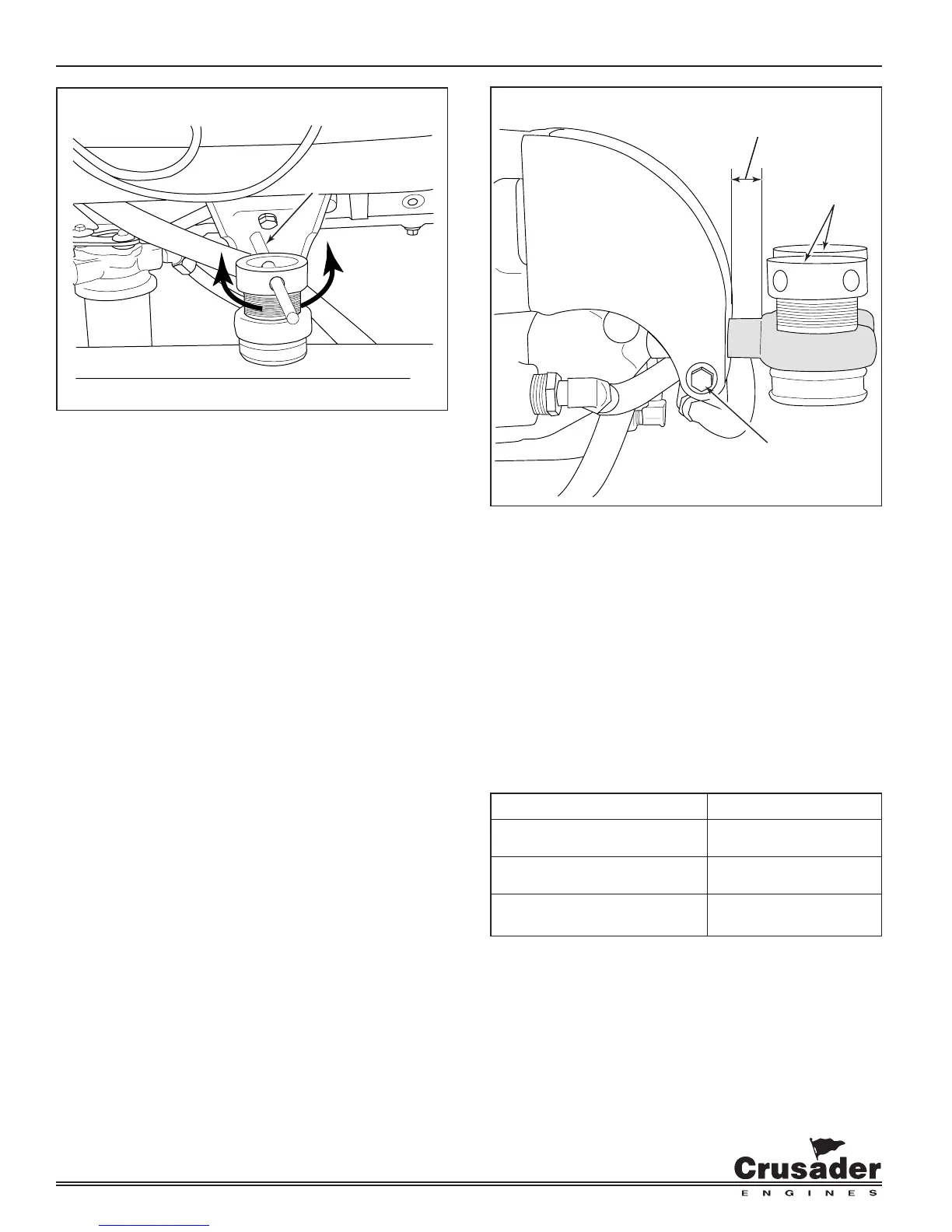
Figure 11-33 Engine Extension
IMPORTANT: The large diameter of the mount trunnion
MUST NOT extend over 1.0 in. (25.4 mm) from the
mounting brackets on any of the mounts.
6. After the engine has been properly aligned,
secure the engine mounts.
7. Connect the propeller shaft coupling to the
transmission coupling. Tighten the coupling
attaching bolts and nuts to the correct
specifi cations.
FASTENER TORQUE SPECIFICATIONS
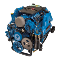
Figure 11-32 Engine Mount Adjustment
5. If the coupling center lines are not aligned, or if
the coupling faces are more than 0.003 in. (0.07
mm) out of parallel, adjust the engine mounts as
follows:
• UP or DOWN ADJUSTMENT: Loosen the lag
bolt 1/4 turn. Use the mount adjusting tool or
a 3/8 in. (0.95 cm) or 1/2 (1.27 cm) diameter
rod through both sides of the adjusting sleeve
to turn. Turn the adjusting sleeve in the
direction required to raise or lower the engine.
After the adjustment is complete, tighten the
lag bolt.
IMPORTANT: Both the front mount (or rear mount)
adjusting sleeves must be turned equally to keep the
engine level from side to side.
• LEFT or RIGHT ADJUSTMENT: Loosen the
trunnion clamping bolt and the nut on all four
mounting brackets. Move the engine to the
left or right, as necessary, to obtain the proper
alignment.
Location Lb-Ft (N
.
m)
Engine Mount to Stringer Securely
Propeller 50 (68)
Trunnion Bolts 45 (61)
ROD
LOWER
ENGINE
RAISE
ENGINE
TRUNNION
BOLT
1.0 in. MAX
(25 mm)
LAG
BOLTS