Assembly
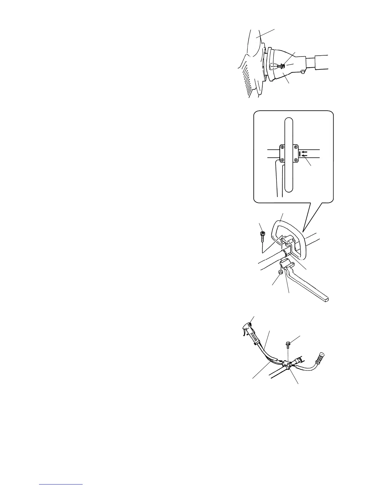
Assembling Engine and Drive Shaft Assembly
Attach the clutch drum housing to the engine using the four
screws supplied with the unit.
Handle Installation
LOOP HANDLE
Loop handle must be assembled gearcase side from the
arrow (A).
【MODEL: BCH25】
1. Slip the rubber sleeve around the shaft.
2. Place the loop handle and the bottom clamp over the rubber
sleeve.
3. Install the four screws and nuts. Tighten the screws evenly.
【MODEL: BCH35】
1. Place the loop handle and the bottom clamp onto the shaft.
2. Install the four screws and nuts. Tighten the screws evenly.
HORN HANDLE
【MODEL: BCH25H and BCH35H】
IMPORTANT: Be careful not to damage the throttle cable
and stop switch wires when you remove the horn handles
from the carton.
1. Loosen the four screws on the top of the clamp bracket.
2. Insert the left and right horn handles into the clamp bracket.
Note that the horn handle with the throttle trigger and stop
switch goes on the right-hand side of the brushcutter.
3. Adjust the horn handles to the desired position, then tighten
the four screws.