14
8.7 Assembling sensors of thermostat
2 and 3
After connecting two additional temperature
sensors, the ecoSTER200 room panel
provides independent temperature regulation
in three rooms. Regulator cooperates with
CT7 type room temperature sensors. Use a
cable with a cross-section of at least 0.25
mm
2
to connect sensors. Recommended
cross-section is 0.5 mm
2
. Cable should not
be longer than 20 m. Sensor cables should
be separated from power cables (~230V). If
not, incorrect temperature readings can
occur. Minimum distance between sensor
cables and power cables should be at least
10 cm.
In order to guarantee a maximum operation
efficiency of the regulator, follow the
recommendations concerning a place of
sensor assembly:
1. Sensors should be assembled on a
height app. 1.5 m over the floor level.
2. Avoid places which are strongly sunlit,
close to heating devices, in direct
vicinity of doors and windows, where
a temperature measurement could be
easily interfered by external
conditions.
3. Avoid places with weak air circulation,
e.g.: behind furniture.
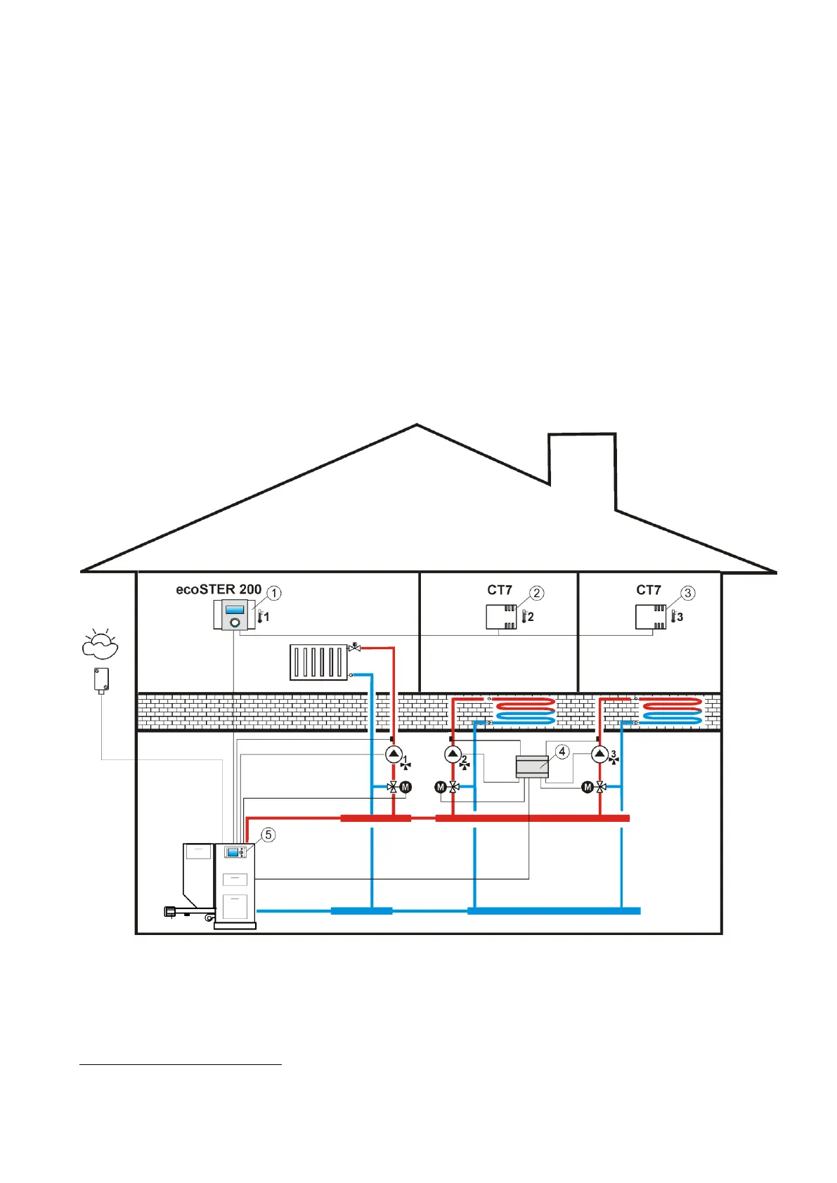
Fig. 8.1
Diagram of cooperation between ecoSTER200 and ecoMAX, where: 1 - ecoSTER200, 2 -
room sensor of thermostat 2 type CT7, 3 - room sensor of thermostat 3 type CT7, 4 – module B
(extends the system by 2 heat circulations), 5 - ecoMAX controller