14
This is the height adjustment to the stand* at the time of setup. The height can be changed among 3 levels in 100
mm units (1770, 1870, and 1970 mm (the maximum height)).
Please lock the casters by pressing the lower portion of the lock buttons of them.
(1) Disconnect the power cable and all other cables.
(2) Take out the printer and remove the printer table.
Please loosen the printer guide fastening screws before removing the printer.
Remove the two M4 screws from bottom side of the printer table and the other two from the rear surface.
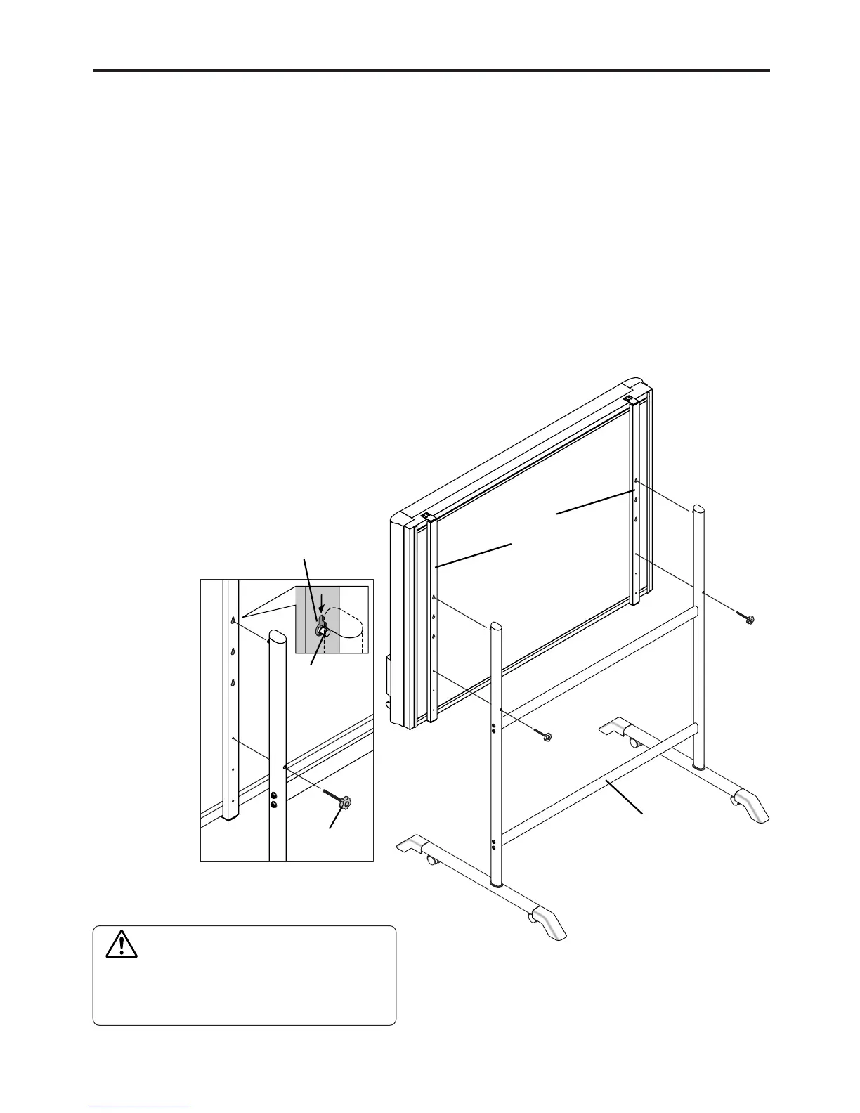
(3) Remove the two locking screws (located at the left and right sides).
(4) Change the hole position of the Copyboard rear frame.
The Copyboard will disengage from the hooks when it is lifted up about 1 cm.
Fully hook the (2 left and right) installation holes of the copyboard
rear frame onto the hooks of the stand.
If a stay (for preventing shaking) is mounted on the printer table,
insert the stay in its original position.
(See (7) on page 5 for mounting instructions.)
(5) Attach the locking screws to the 2 locations (left and
right) and tighten to the rear frames.
(6) Return to original by following the steps in reverse.
9. CHANGING THE HEIGHT OF THE UNIT
*The printer may be an option.
CAUTION
Please have 2 or more persons lift the copyboard
when installing it or making a height adjustment.
If the unit is dropped or falls over, this could cause
unforeseen injury.
Mounting hole
Hook
lock-screw
Rear frames
Stand