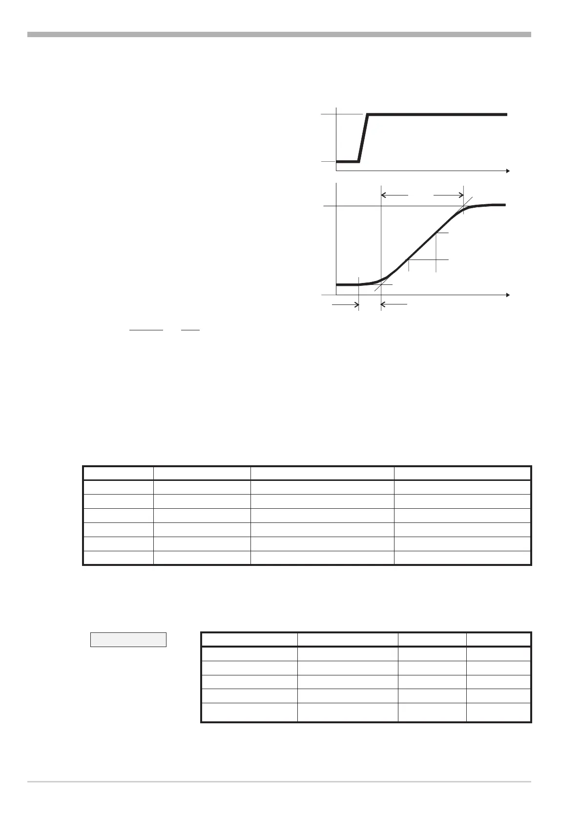
Values T
g
and x
max
(step change from 0 to 100 %) or Dt and D x (partial step re
-
sponse) can be used to determine the maximum rate of increase v
max
.
y =correcting variable
Y
h
= control range
Tu = delay time (s)
Tg = recovery time (s)
X
max
= maximum process value
V
max
=
Xmax
Tg
=
{
{
x
t
= max. rate of increase of process value
The control parameters can be determined from the values calculated for delay
time T
u
, maximum rate of increase v
max
, control range X
h
and characteristic K ac-
cording to the formulas given below. Increase Xp, if line-out to the set-point os-
cillates.
Operation
KS40-1 burner 12 Manual tuning
Tu
Tg
t
x
100%
0%
t
Y
h
X
max
{X
{t
Parameter adjustment effects
Parameter Control Line-out of disturbances Start-up behaviour
Pb1 higher increased damping slower line-out slower reduction of duty cycle
lower reduced damping faster line-out faster reduction of duty cycle
td1 higher reduced damping faster response to disturbances faster reduction of duty cycle
lower increased damping slower response to disturbances slower reduction of duty cycle
ti1 higher increased damping slower line-out slower reduction of duty cycle
lower reduced damping faster line-out faster reduction of duty cycle
Formulas
K = Vmax * Tu controller behavior Pb1 [phy. units] td1 [s] ti1 [s]
With 2-point and
3-point controllers,
the cycle time must be
adjusted to
t1 / t2 £ 0,25 * Tu
PID 1,7*K 2*Tu 2*Tu
PD 0,5 * K Tu OFF
PI 2,6 * K OFF 6*Tu
PKOFF OFF
3-point-stepping 1,7 * K Tu 2 * Tu
 Loading...