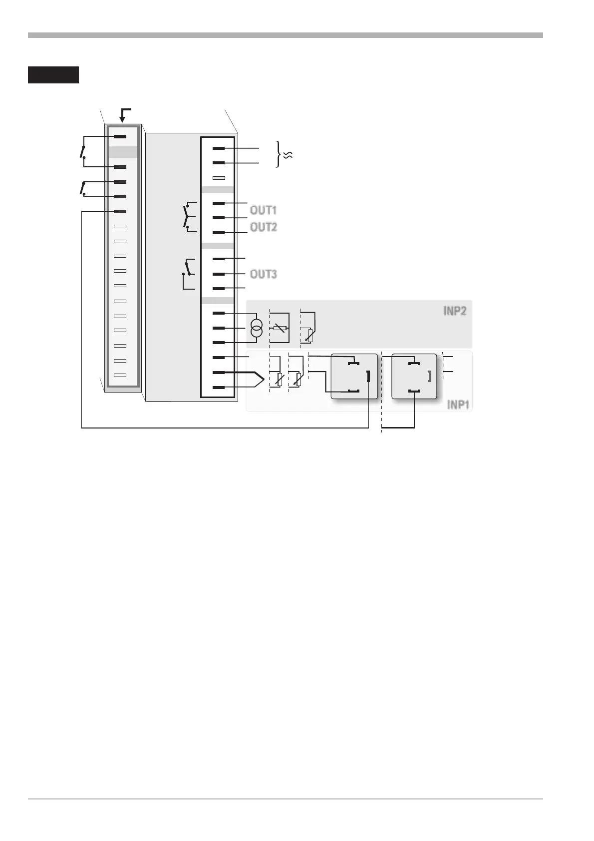
2 Electrical connections
* Safety switch INP1 (mA i 10V) in position 10V
** Safety switch INP1 (mA i 10V) in position mA/Pt
Connection of input INP1
Input for variable x1 (process value)
a thermocouple
b resistance thermometer (Pt100/ Pt1000/ KTY/ ...)
c Transducer 50-30-50 W
d voltage (0/2...10V)
e pressure transmitter (3-wire connection)
f pressure transmitter (2-wire connection)
g current (0/4...20mA)
Connection of input INP2
See input INP1.
Connection of inputs di2/di3
Digital input di2 for external switching between SP and SP.2 (SP/SP2).
Digital input di3 for external switching between 3-point-stepping controller and
on/off controller (DPS/SG).
Electrical connections
KS40-1 burner 6
L
N
90...250V
OUT1
di2
di3
OUT2
OUT3
INP2
U(+)
t
1
3
4
5
6
(2)
1
2
3
4
5
6
7
8
9
10
11
12
13
14
15
10V *
20mA **
INP1
2
3
1
1
2
+
+
ab
b
c
c
edf
g
gh
++
--
100%
100%
0%
0%
ption
A
P
 Loading...