28
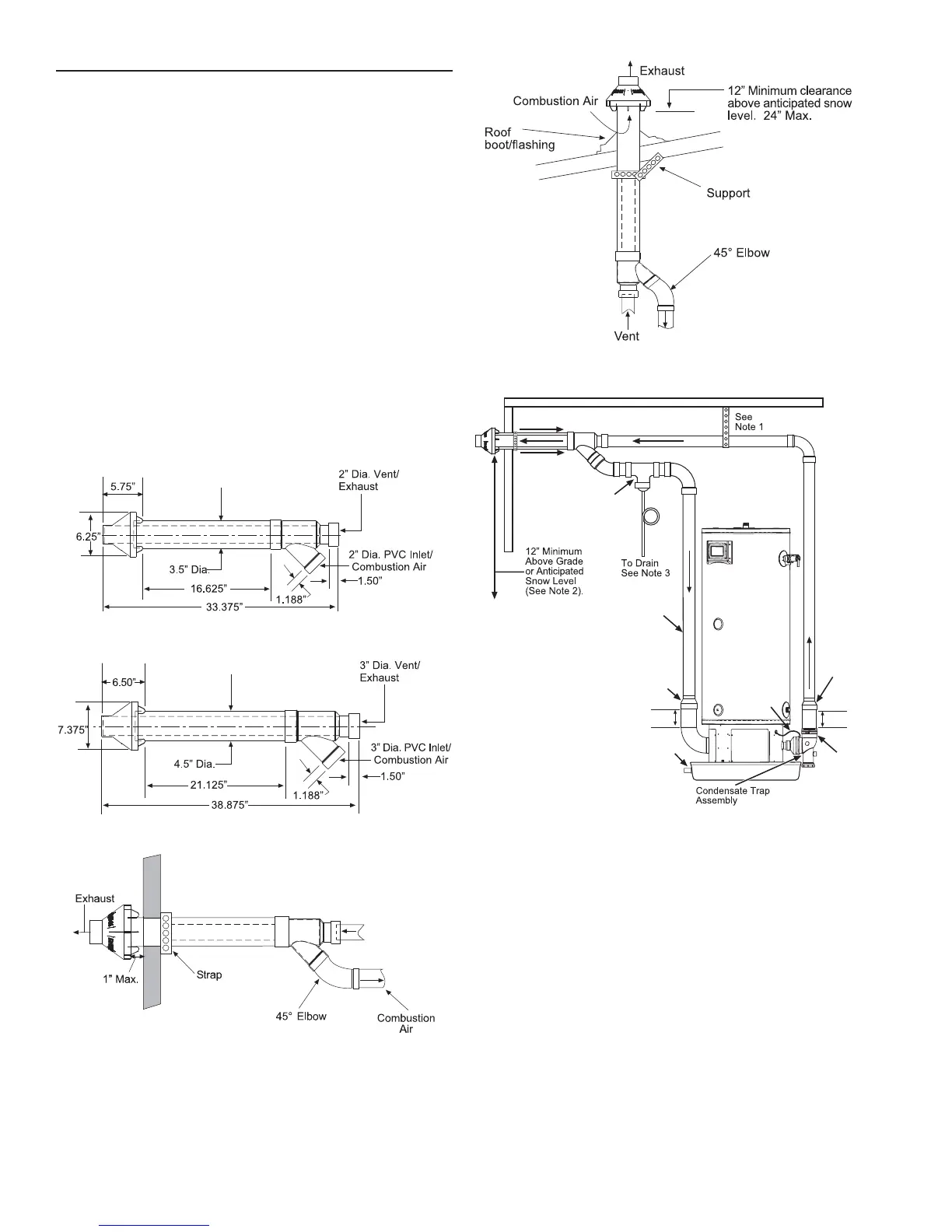
CONCENTRIC VENT INSTALLATION
)RU QHZ LQVWDOODWLRQV RI %78KU
XQLWVLQVWDOO´&RQFHQWULFYHQWNLWPRGHO.*$97&97SDUW
QXPEHU)RUQHZLQVWDOODWLRQVRI
EWXKUXQLWVLQVWDOO´&RQFHQWULFYHQWNLWPRGHO.*$97&97
SDUW QXPEHU 6HH 0DQXIDFWXUHU¶V LQVWUXFWLRQV IRU
FRPSOHWHLQVWDOODWLRQRUFDOOWKHWHFKQLFDOVXSSRUWQXPEHUOLVWHG
RQ WKH EDFN FRYHU RI WKLV PDQXDO )RU SODQQLQJ SXUSRVHV VHH
)LJXUHVWKURXJKEHORZIRUYHQWWHUPLQDOVSHFLILFDWLRQV
Note: :KHQWHUPLQDWLQJFRQFHQWULFYHQWVIRUDGGLWLRQDOXQLWVDOO
PRGHOVVHH³9HQWLQJ0XOWLSOH8QLWV´RQ3DJH
)LHOG VXSSOLHG SLSH DQG ¿WWLQJV DUH UHTXLUHG WR FRPSOHWH WKH
installation.
SAFETY CONSIDERATIONS
,QVWDOOLQJDQGVHUYLFLQJZDWHUKHDWLQJHTXLSPHQWFDQEHKD]DUGRXV
GXH WR JDV DQG HOHFWULFDO FRPSRQHQWV ,QVWDOODWLRQ DQG VHUYLFH RI
WKHFRQFHQWULFYHQWWHUPLQDWLRQUHTXLUHVDELOLW\HTXLYDOHQWWRWKDWRI
DTXDOL¿HG LQVWDOOHU RU TXDOL¿HG VHUYLFHWHFKQLFLDQ VHH3DJH $OO
SUHFDXWLRQVLQWKHOLWHUDWXUHRQWDJVDQGODEHOVDWWDFKHGWRWKHXQLW
PXVWEHREVHUYHG
)ROORZDOOVDIHW\FRGHV:HDUVDIHW\JODVVHVDQGZRUNJORYHV
Figure 26. 2 Inch Concentric Vent
Figure 27. 3 Inch Concentric Vent
Figure 28. Through the Wall Termination
Figure 29. Through the Roof Termination
Tee with
Drain Trap
See Note 4
Trap
NOTES:
1. Support Horizontal Pipe Every Four Feet.
Support Vertical Pipe Every Six Feet.
2. Increase The 12” Minimum Above
Grade To Keep Inlet Opening
Above Anticipated
Snow Levels.
3. Slope All Piping 1/8” Per
Foot
Down Toward The
Water Heater.
4. For units with inputs of
150,000 BTU/hr
and below,
use 2" or 3" pipe. For units
with
inputs of
175,000 BTU/hr
and above,
use only 3" pipe.
5. When venting with 2" pipe, a sufficient
length of 3" pipe (6" minimum) must be
inserted into the exhaust and inlet elbow
assembly before transitioning down to
2" pipe with a 3" x 2" reducer.
6. Connect blocked pressure switch hose
to condensate trap.
See Note 5
See
Note 6
Drain Pan
(Piped to
Adequate
Drain)
3" x 2"
Reducer
Exhaust
Elbow
Assembly
See Note 5
3" x 2"
Reducer
Figure 30. Concentric Vent Piping Installation
 Loading...