
K
Krista OliverJul 31, 2025
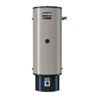
What to do if my Polaris Water Heater doesn't have enough hot water?
- LlharrisJul 31, 2025
If you're not getting enough hot water from your Polaris Water Heater, here are a few things to check: * Ensure the breaker and fuses are working. * Verify the Enable/Disable switch is in the “enable” position. * Make sure the hot water supply valves to fixtures are open. * Adjust the Operating Set Point or Differential setting if they are not optimal. * Adjust Temperature Probe Offset setting, if it is causing premature termination of heating cycles. * Allow the water heater to heat water as per demand, if the heating capacity has been exceeded. * Check for leaks and close any open faucets.