LOCATION
OF
MAIN
COMPONENTS
AND
CONTROLS
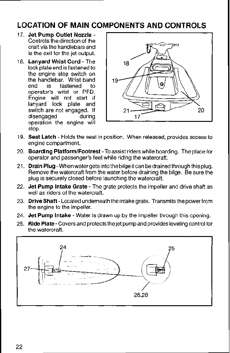
17.
Jet Pump Outlet Nozzle
-
Controls the direction of the
craft via the handlebars and
is the exit for the jet output.
18.
Lanyard Wrist Cord
-
The
lock plate end is fastened to
the engine stop switch on
the handlebar. Wrist band
end is fastened to
operator's wrist or
PFD.
Engine will not start if
lanyard lock plate and
switch are not engaged. If
disengaged during
operation the engine will
stop.
19.
Seat Latch
-
Holds the seat in position. When released, provides access to
engine compartment.
20.
Boarding PlatformlFootrest
-
To assist riders while boarding. The place for
operator and passenger's feet while riding the watercraft.
21.
Drain Plug
-
When water gets into the bilge it can be drained through this plug.
Remove the watercraft from the water before draining the bilge. Be sure the
plug is securely closed before launching the watercraft.
22.
Jet Pump lntake Grate
-
The grate protects the impeller and drive shaft as
well as riders of the watercraft.
23.
Drive Shaft
-
Located underneath the intake grate. Transmits the power from
the engine to the impeller.
24.
Jet Pump Intake
-
Water is drawn up by the impeller through this opening.
25.
Ride Plate
-
Covers and protects the jet pump and provides leveling control for
the watercraft.
 Loading...