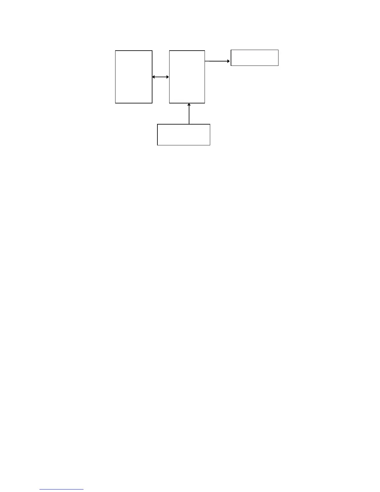
Audible Alarm
Detector Processor
Power Supply
Figure 2 − PM1701M Block Diagram
The detector unit includes:
- CsI(Tl) scintillator with photodiode;
- amplifier-converter board.
The scintillator-photodiode transforms gamma-quanta into electric pulses that
come to the amplifier-converter. The amplifier-converter transforms these signals
into quasi-Gauss pulses that come to the processor unit.
The processor unit includes:
- processor;
- non-volatile memory;
- LCD;
- control buttons;
- IR transceiver;
- built-in audible alarm;
- light alarm.
The 16-bit RISC-based processor is used to: test of the instrument upon power
on; process data; control all operating modes; display processed information on LCD;
control audible alarms; monitor battery voltage.
The non-volatile memory is used to log operating history of the instrument:
count rate in preset intervals; alarm events; background re-calibration events; power
on/off events.
The following parameters are also stored in the memory: instrument serial
number; audible alarm on/off information; coefficient n value; current date and time;
count rate data logging intervals; count time in the background calibration mode;
count time in the search mode; other parameters according to the user software.