
R
Robert PearsonAug 6, 2025
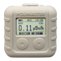
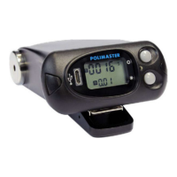
What to do if there are no indications on the LCD of Polimaster PM1603A?
- HhallmarissaAug 6, 2025
If there are no indications on the LCD, it could be due to battery discharge or incorrect battery insertion. Replace the battery, and ensure it is inserted correctly.