3 4
1 POWER FILTER INSTALLATION (Reference Page 3, Fig. 1)
FIG. 2
7
8
A. First, remove the Seal Top Retainer (10), Seal Top (9), and
Filter Cartridge (15) from the assembled Filter Case.
Lubricate the pump O-ring with petroleum jelly. Hold
the filter case (8) securely, and insert motor pump so
that the outlet on the volute housing extends out of the
opening in the side of the filter case. Insert the motor
pump until the two ribs on the inlet of the volute housing
protrude through the bottom of the filter case. Reach
down inside the filter case and place the Pump Retaining
Nut (7) over the top of the volute housing inlet. Twist the
Nut (7) clockwise until it is snug. See Fig. 2.
B. Get the Suction and Return Hoses (12, 13), and remove two Hose
Clamps (14), from the hardware bag. Loosen the hose clamps and
slide them over one end of each hose. Lubricate O-rings (24) on the
Filter Case (8) and Volute Housing liberally with petroleum jelly.
Install one hose on the filter case suction inlet at the top, and one
hose on the filter case return outlet at the base. Tighten both of the
Hose Clamps (14).
C. Locate the Return Fitting assembly parts (21, 25-28). Lubricate the
(black) RF Gasket (26) liberally with petroleum jelly and install it over
the threads on the Return Fitting (25). Insert the Return Fitting (25)
with the RF Gasket (26) through the pool return fitting hole in the
wall from the inside of the pool, see Fig. 3 for correct location. Thread
the RF Nut (27) onto the fitting until it is hand tight. DO NOT
over tighten the RF Nut or the RF Gasket (26). Plug the pool’s Return
Fitting (25) with the RF Plug (21) from the inside of the pool. Set the
RF Diverter Fitting (28) aside for later installation. Now locate the
Pool Suction Fitting assembly parts (16-20). Lubricate the (black) SF
Gasket (17) liberally with petroleum jelly and install it over the threads on the Suction Fitting (16). Insert the
Suction Fitting (16) with SF Gasket (17) through the pool suction fitting hole in the wall from the inside of the
pool. Place the (white) SF Thrust Washer (18) over the Suction Fitting and then thread the SF Nut (19) onto the
fitting until it is hand tight. DO NOT over tighten the SF Nut or wrinkle the pool wall around the SF Thrust
Washer (18) or the SF Gasket (17). Cap the pool’s Suction Fitting (16) with the SF Water Cap (20). Only hand
tighten the Water Cap (20). Start filling pool.
D. After the pool is filled, position the Filter Assembly between the two fittings on the side of the pool, about 6
inches out from the base. The suction hose (12), coming from the top of the filter case should be facing the right,
and the return hose (13) coming from the pump, on the lower side of the case, should be facing the left; see Fig.3.
E. Slip both of the remaining Hose Clamps (14) over the ends of the two hoses. Lubricate O-rings (24) on the wall
fittings liberally with petroleum jelly then connect the hoses to the Suction and Return wall fittings located on
the side of the pool. The Pool Suction Fitting is on the right, and the return fitting is on the left, see FIG. 3. Secure
both of the hoses in place by tightening the two Hose Clamps (14).
F. Unscrew the Vent Screw (11) from the Seal Top (9) about 1-1/2 turns. NOTE: VENTING THE SYSTEM IS NECESSARY
FOR AIR TO ESCAPE AS THE FILTER CASE FILLS WITH WATER.
G. Remove the RF Plug (21) from the return fitting (25) on the inside of the pool. Also remove the SF Water Cap (20)
from the Suction Fitting (16). This allows the filter system to fill with water. DO NOT discard the RF Plug (21) and
the SF Water Cap (20). You will need them when you change the Filter Cartridge or service the pump. When full,
water should be coming out of the groove of the vent screw. Hand-tighten the vent screw into the seal top until
the O-Ring seals around the screw and no more water is escaping.
FIG. 3
POOL
RETURN
FITTING
POOL
SUCTION
FITTING
14
14
11
13 12
9
8
Should you encounter any problems, contact the Customer Service at (888) 919-0070 from 8 AM to 5 PM Mon. thru Fri.
EST. Extended operating days and hours during peak season requirements.
Should you encounter any problems, contact the Customer Service at (888) 919-0070 from 8 AM to 5 PM Mon. thru Fri.
EST. Extended operating days and hours during peak season requirements.
RP800 Filter System with F700C Pump
RP1000 Filter System with F1000C Pump
RP1000 Filter System with F1500C Pump
RP2000 Filter System with F2000C Pump
57 watts
80 watts
120 watts
210 watts
1.1 amps
2.2 amps
2.2 amps
2.2 amps
Pump System Wattage Amperage
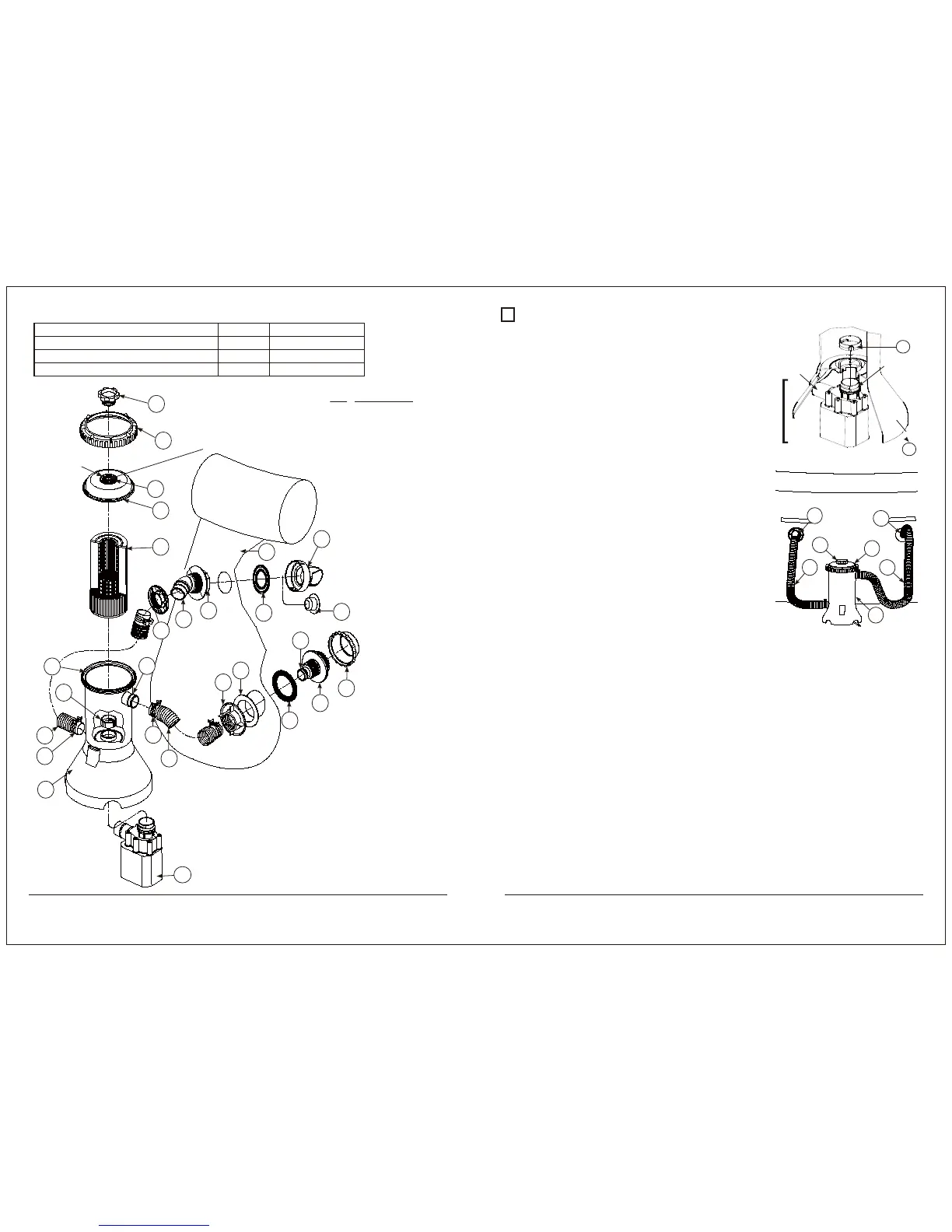
Volute
Housing
Outlet
Motor Pump
Volute
Housing
Inlet
FIG. 1
THE FILTER CARTRIDGE (15) WILL HOLD 1”
DIAMETER CHLORINE TABLETS. CHECK
YOUR CHLORINE LEVELS TO DETERMINE
THE PROPER NUMBER OF TABLETS TO ADD.
LIBERALLY
LUBRICATE
THE O-RINGS
(17,22,23,24 &26)
WITH SOME
PETROLEUM
JELLY
PATENTED
FILTER
CARTRIDGE
SYSTEM #7,005,062
KEY DESCRIPTION
1-6 MOTOR PUMP
7 PUMP RETAINING NUT
8 FILTER CASE
9 SEAL TOP
10 SEAL TOP RETAINER
11 VENT SCREW
12 SUCTION HOSE
13 RETURN HOSE
14 HOSE CLAMPS
15 FILTER CARTRIDGE
16 SUCTION FITTING (SF)
17 SF GASKET (Black)
18 SF THRUST WASHER (White)
19 SF NUT
20 SF WATER CAP (Use for service only)
21 RF PLUG (Use for service only)
22 O-RING (On Filter Case)
23 O-RING (On Vent Screw)
24 O-RING (On Hose Connections)
25 RETURN FITTING (RF)
26 RF GASKET (Black)
27 RF NUT
28 RF DIVERTER FITTING
29 POOL WALL
11
10
23
9
15
27
22
7
13
14
4 Ea.
4 Ea.
8
12
14
24
19
18
16
20
17
1-6
25
24
26
24
21
28
29
]Volute Housing