Page 7 of 20
March 2024
PJN3 SERIES
RECIRCULATING FLUSH
WASTE HOLDING TANK INSTALLATION:
INSTALLATION OF STATIC TANK: Refer to Figure 3. Position the tank so that it is centered
between the left and right side wall panels and pushed up to the floor plate. There are drill
spots on each of the side wall panels. The top four in-line drill spots on the rear wall panel are
used to rivet the back of the holding tank to the rear wall panel. Of the top four drill spots on
each of the side wall panels, only the two closest to the rear are used to rivet the sides of the
holding tank to the side wall panels. While pushing the wall panels in flat against the tank, use
a 13/64” drill bit. Drill through the specified drill spots of the wall panels into the outer walls of
the tank. CAUTION: DRILL ONLY THROUGH THE OUTER WALL OF THE HOLDING
TANK. DO NOT DRILL THROUGH THE INSIDE TOP SURFACES OF THE TANK. From
the outside of the restroom one person will rivet through the drilled holes with PC-000103 rivets,
while another person inside the restroom puts PC-000106 back-up washers on the rivet stems.
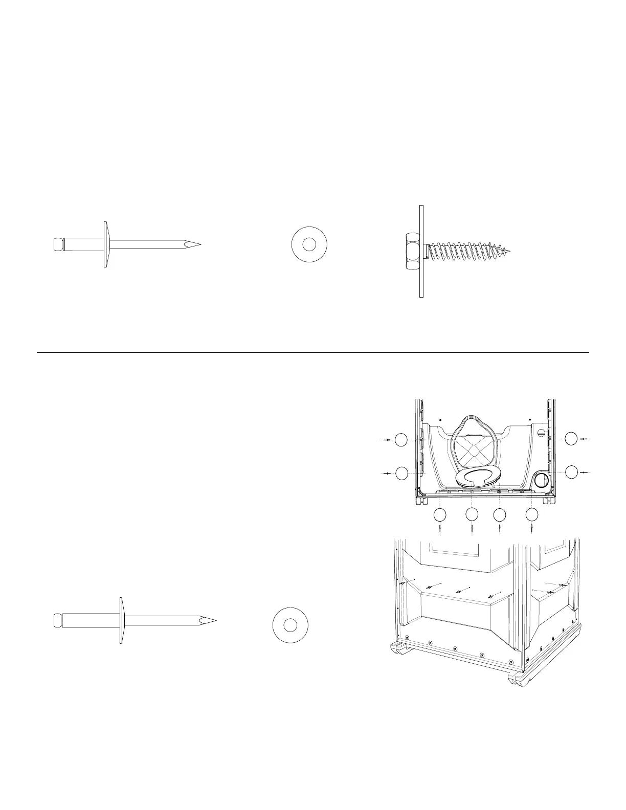
STEP 7:
CABANA ASSEMBLY:
Position the three side panels and corner molding sub-assembly around the base skid. IMPORTANT - The walls of the cabana should be approximately 1/4”
from the top surfaces of the base skid. Place 1/4” thick shims between the rear corners of the cabana, and the base skid; this will make the
cabana structure level with the front assembly. To connect the front assembly, corner moldings, and side panels, begin at the front of the restroom. Insert a PC-
000100 rivet through the center hole, while attaching a PC-000106 back-up washer from the back. Repeat for the remaining holes. (For a uniform visual appearance, drive
all rivet heads from the front). CAUTION: DO NOT PRE-DRILL HOLES IN THE BASE SKID; THE PC-000192 SEMS LAG SCREWS ARE SELF-THREADING.
DO NOT OVER-TIGHTEN THE SEMS LAG SCREWS; TIGHTEN ONLY UNTIL SNUG. On the bottom of each wall panel, there are five predrilled holes, begin at
the center hole of the rear panel. Use a 7/16” socket wrench, while pushing the rear wall panel against the base skid, drive-in the lag screws. Then continue with the side
wall panels, starting with the front edge of each side, working towards the back.
STEP 6:
PC-000100 Rivet
18 used in this step
PC-000106 Washer
18 used in this step
PC-000192 Sems Assembly
15 used in this step
PC-000103 Rivet
8 used in this step
PC-000106 Washer
8 used in this step
ASSEMBLY INSTRUCTIONS
1
2
5
6
7
8
4
3
Figure 6
 Loading...