2SHUDWLQJWKH9LEURPHWHU
7KH,QGLY LGXDO0HQXV
0HQX, 1752
After switching on or RESET, the controller shows that it is ready to operate
with the menu INTRO. It is not possible to change back to this menu as it
does not have a control function.
0HQX&21),*
This menu provides information on the decoders and interfaces installed. The
individual configurations are described in the following.
9HORFL W\'HFRGHU
This line shows the velocity decoders installed and the number of available
velocity measurement ranges. The following abbreviations are used for the
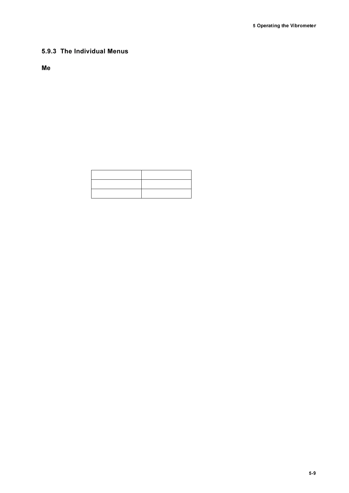
individual decoders:
Example:
5PLL + 4HF means that the velocity decoder OVD-01 is installed with 5 veloc-
ity measurement ranges and the velocity decoder OVD-02 is installed with 4
velocity measurement ranges.
'LVSOD FHPHQW'H FRG HU
This line is only present if a displacement decoder is installed. This line shows
the number of available displacement measurement ranges.
5HPRWH)RFXV
This line shows whether the option REMOTE FOCUS is installed. With this
option the laser beam can be remotely focused using the sensor head OFV-
303 (refer to section 5.4).
,((( %XV ,Q WHUID FH
When operating the vibrometer via the IEEE-488/GPIB interface on the back
of the controller in this line the instrument address can be set in the range
. The preset address is
(refer to appendix E).
6HUL DO, QW HUID FH
When operating the vibrometer via the RS-232 interface on the back of the
controller it is possible to switch between the transfer rates
%DXG
and
%DXG
(refer to appendix E).
Table 5.1: Abbreviations of the individual velocity decoders
$EEUHY LDW LRQ
'HFRGHU
PLL OVD-01
HF OVD-02