&
&%DVLFVRIWKH0HDVXUHPHQW3UR FHGXUH
&2SWLFDO&RQILJXUDWLRQLQWKH6HQVRU+HDG2)9
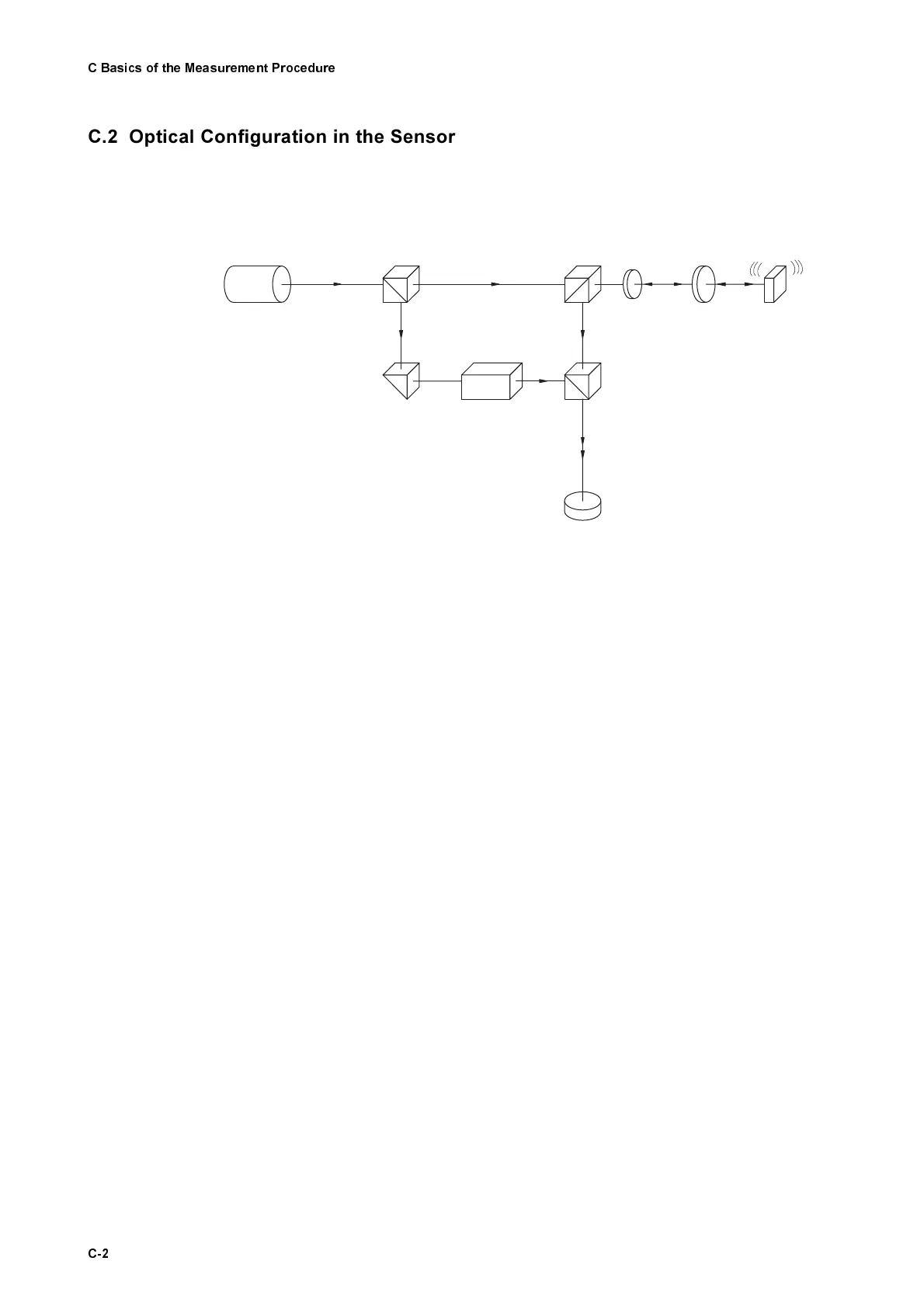
In Polytec’s vibrometers, the velocity and displacement measurement is car-
ried out using a modified Mach-Zehnder interferometer. The optical configura-
tion in the sensor head OFV-303/-353 is shown schematically in figure C.1.
The light source is a helium neon laser which provides a linear polarized
beam. The polarizing beam splitter BS1 splits the beam into the object beam
and the reference beam.
The object beam passes through the polarizing beam splitter BS2 as well as a
λ
/4 plate, is then focused by the lens on the object and scattered back from
there. The polarizing beam splitter BS2 then functions as an optical direc-
tional coupler together with the
λ
/4 plate, and deflects the object beam to the
beam splitter BS3. As both arms of the "internal" interferometer are symmetri-
cal, the optical path difference between the object beam and the reference
beam vanishes within the interferometer. The resulting path difference is
equal to twice the distance between the beam splitter BS2 and the object.
The Bragg cell in the reference arm of the interferometer generates the addi-
tional frequency offset to determine the sign of the velocity.
The resulting interference signal of the object beam and reference beam is
converted into an electrical signal in the photo detector and subsequently
decoded in the controller.
Figure C.1: Optical configuration of the interferometer in the sensor head OFV-303/-353
BS 1
Lens
Object
Prism
Bragg C ell
BS 3
BS 2Laser
Detector
R eference
Beam
Object Beam
λ/4