'
')XQFWLRQDO'HVFULSWLRQRIWKH&RQWUROOHU
done by an electronic circuit to regenerate high frequency signals based on
the principle of the phase locked loop (PLL).
The principle of signal regeneration by the tracking filter is based on replacing
the input signal with a distorted amplitude by a stable signal from a voltage
controlled oscillator which is synchronized with the frequency and the phase
of the input signal. Suitable circuit design can make it possible to maintain the
synchronized condition approximately, even if the input signal is temporarily
lost. The mechanical analog for this design is a flywheel which may lose a
small portion of its energy if the driving force is briefly interrupted but contin-
ues to run at almost the same number of revolutions per minute and can drive
a subsequent mechanism without disruption. It is easy to see that this effect
gets better, the higher the inertia of the wheel is. At the same time the fly-
wheel however loses the ability to follow rapid changes in the revolutions per
minute i.e. the dynamic response of the drive system gets worse. The same
correlation also applies to the electronic tracking filter which thus always rep-
resents a compromise between the regeneration effect and the dynamic
tracking behavior of the input signal. Basically, good drop-out elimination or
noise suppression is always involved with limited dynamic response. If the
maximum acceleration is exceeded, the synchronization between the input
signal and the oscillator is lost (the tracking filter loses lock) which leads to
drastic signal distortions at the signal output. Practical advice for setting the
tracking filter can be found in section 4.2.2 and section 4.2.3.
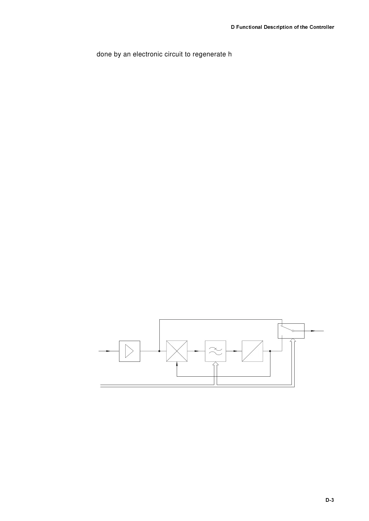
The internal structure of the tracking filter circuit is shown in figure D.2. The
function of the voltage controlled oscillator (VCO) has already been men-
tioned. The control signal which synchronizes the oscillator is generated in
the phase detector which monitors the phase difference between the input
signal and the oscillator signal. The dynamic characteristics of the configura-
tion are mainly determined by the internal low pass filter. The maximum accel-
eration which the tracking filter can still follow depends on the filter bandwidth.
The low pass time constant is switched between SLOW and FAST via the sys-
tem control and thus adapts the dynamic characteristics to the application.
The tracking filter can be turned off via a bypass if the accelerations are too
high or in the case of good optical signals.
'RZQPL[LQJ
RIWKH
IUHTXHQF\
Down-mixing of the frequency in the input section is required to convert the
carrier frequency of the FM signal from 40MHz originally to lower intermedi-
ate frequencies. With these intermediate frequencies, the velocity decoder
can work optimally in the individual measurement ranges. Down-mixing is car-
ried out by a mixing process which does not affect the modulation content of
the FM signal. The variable frequency f
LO
is produced by the so-called local
oscillator in a fixed relationship to the drive frequency of the Bragg cell.
Figure D.2: Block diagram of the tracking filter circuit
Am plifier
Input
Phase
detector
Low pass
filte r
V
f
VCO
off
on
O utput
C ontrol Bus