In Polytec’s vibrometersIn Polytec’s vibrometers, the , the velocity and displacement measurement isvelocity and displacement measurement is
carried out using a modified Mach-Zehnder interferometer. The opticalcarried out using a modified Mach-Zehnder interferometer. The optical
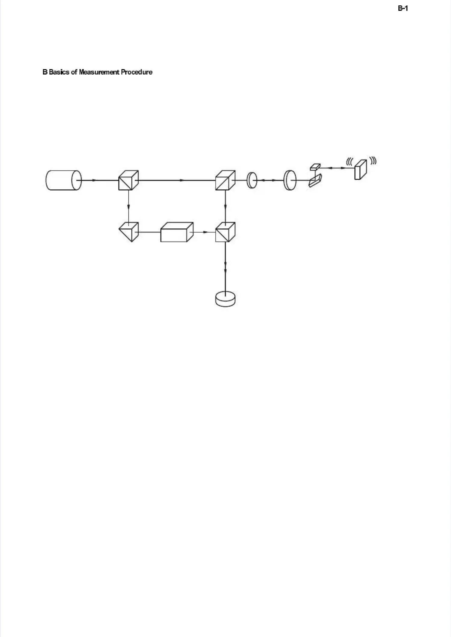
configuration in the scanning head is configuration in the scanning head is shown schematically inshown schematically infi
figugurere B.B.11..
The light source is The light source is a helium neon laser, which provides a linear a helium neon laser, which provides a linear polarizedpolarized
beam. The polarizing beam splitter BS1 splits the beam into beam. The polarizing beam splitter BS1 splits the beam into the object beamthe object beam
and the reference beam.and the reference beam.
The object beam passes through the polarizing beam splitter BS2 as well as aThe object beam passes through the polarizing beam splitter BS2 as well as a
λλ
/4-p/4-platelate, is , is then then focufocussed ssed by tby the lhe lens ens on ton the ohe objecbject ant and scad scatterttered bed back fack fromrom
there. The polarizing beam splitter BS2 then functions as an there. The polarizing beam splitter BS2 then functions as an opticaloptical
directional coupler together with thedirectional coupler together with the
λλ
/4-p/4-platelate, and defl, and deflects the oects the objecbject beam tot beam to
the beam splitter BSthe beam splitter BS3. As both arms of the3. As both arms of the ’internal' interf’internal' interferometer areerometer are
symmetricsymmetrical, the optical path difference between the object beam al, the optical path difference between the object beam and theand the
reference beam vanishes within the reference beam vanishes within the interferometinterferometer. The resulting pather. The resulting path
difference is equal to twice the distance between the beam splitter BS2 anddifference is equal to twice the distance between the beam splitter BS2 and
the object.the object.
The Bragg cell in The Bragg cell in the reference arm of the the reference arm of the interferometer generates theinterferometer generates the
additional frequency offset to determine the sign of the velocity.additional frequency offset to determine the sign of the velocity.
The resulting interference signal of the object beam The resulting interference signal of the object beam and reference beam isand reference beam is
converted into an electrical signal in the converted into an electrical signal in the photo detector and subsequentlyphoto detector and subsequently
decoded in the controller.decoded in the controller.
Figure B.1: Optical configuration in the scanning headFigure B.1: Optical configuration in the scanning head
 Loading...


