The main function of the controller is to demodulate the radio frequency signalThe main function of the controller is to demodulate the radio frequency signal
(RF signal) provided by the (RF signal) provided by the interferometeinterferometer in r in the scanning head. Thethe scanning head. The
frequency of the signal is frequency of the signal is the carrier of the the carrier of the velocity informationvelocity information. Secondary. Secondary
functions such as human interfacing, display and filters improve the functions such as human interfacing, display and filters improve the useruser
friendliness of the system. An overview of the functional structure of thefriendliness of the system. An overview of the functional structure of the
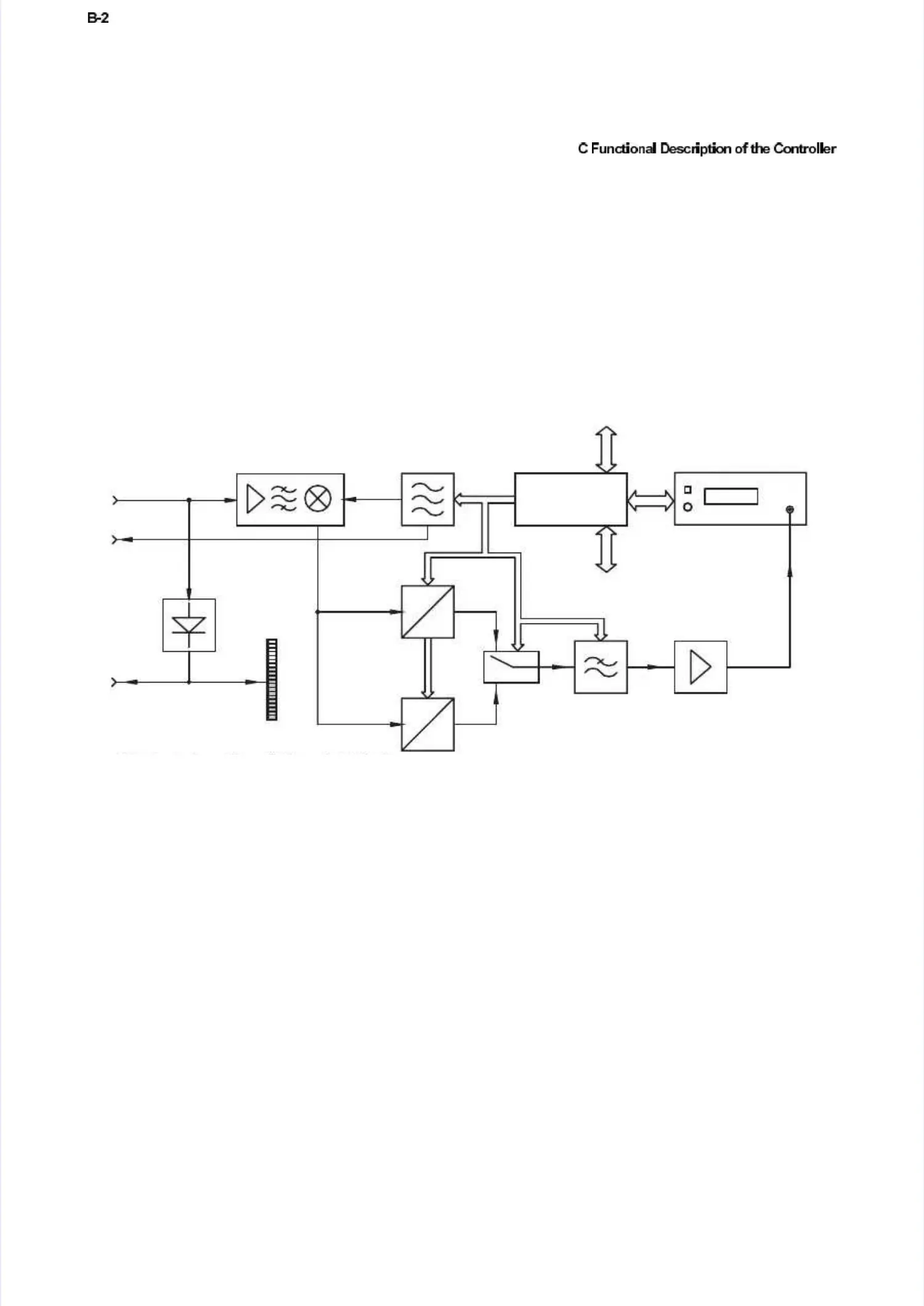
controller is shown incontroller is shown infi
figugurere C.C.11..
The RF signal from the The RF signal from the scanning head (sensor input) initially passes thescanning head (sensor input) initially passes the
functional block signal conditioning where it is pre-processed to optimallyfunctional block signal conditioning where it is pre-processed to optimally
drive the following drive the following blocks. Subsequentlblocks. Subsequently follows the y follows the velocity signal decoding.velocity signal decoding.
If the controller is fully If the controller is fully equipped there are two velocity decoders installedequipped there are two velocity decoders installed
(demodulator I and demodulator II).(demodulator I and demodulator II).
The velocity is modulated on the radio frequency of the input signal. In theThe velocity is modulated on the radio frequency of the input signal. In the
velocity decoder, an AC-voltage is generated which is proportional to thevelocity decoder, an AC-voltage is generated which is proportional to the
instantaneous velocity of the object with the aid of so-called FM-instantaneous velocity of the object with the aid of so-called FM-
demodulators.demodulators.
The individual demodulators require different reference frequencies which areThe individual demodulators require different reference frequencies which are
in a fixed relationship to the driver frequency of the Bragg cell in thein a fixed relationship to the driver frequency of the Bragg cell in the
interferometer. They are generated in the central oscillator block,interferometer. They are generated in the central oscillator block,
synchronized with the driver signal for the synchronized with the driver signal for the Bragg cell.Bragg cell.
The velocity decoder is followed by a low pass filter which suppressesThe velocity decoder is followed by a low pass filter which suppresses
spurious RF components and limits the bandwidth of the output signal spurious RF components and limits the bandwidth of the output signal toto
reduce background noise. Via the system control, various cutoff frequenciesreduce background noise. Via the system control, various cutoff frequencies
can be set can be set for the low pass filter.for the low pass filter.
The last block in each signal path is an amplifier which scales the outputThe last block in each signal path is an amplifier which scales the output
signals and can optimally drive subsequent signal processing units.signals and can optimally drive subsequent signal processing units.
Figure C.1: Block diagram of the controller OFV-3001SFigure C.1: Block diagram of the controller OFV-3001S
 Loading...


