16
6. APPeNdIX
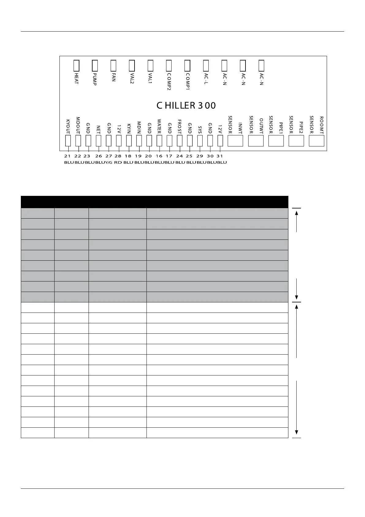
6.1 Connection of PCB illustration
6.2 Connections explanation
CHILLER 300
240 VAC 50Hz.12 VDC
Wire No. Port No. Symbol Meaning
11 HEAT Auxillary heater output (220VAC)
10 PUMP Demand pump ouput (220VAC)
9 FAN Fan motor output (220VAC)
8 VAL2 4way valve of system2 (220VAC)
7 VAL1 4way valve of system1 (220VAC)
6 COMP2 Compressor of system2 (220VAC)
5 COMP1 Compressor of system1 (220VAC)
4 AC-L Active power supply
1,2,3 AC-N Neutral wire
21 12 KYOUT GND On/Off switch (output) (not used)
22 13 MDOUT GND Mode output (not used)
26,27,28 14,15,16 NET GND 12V Wire controller
18 18 KYIN On/Off Switch (input)(not used)
19 19 MDIN Model (input) (not used)
16,17 21,22 WATER GND Flow switch (input)( normal close)
24,25 23,24 FROST GND Defrost signal (not used)
29,30,31 25,26,27 SYS GND 12V System protection (input)(normal close)
32 ROOMT Ambient temp. (input)
31 PIPE2 Temp. Of fan coil2 (input) (not used)
30 PIPE1 Temp. Of fan coil 1 (input) (not used for split type)
29 OUTWT Water out temp. (input)
28 INTWT Water in temp. (input)
1
2
3
4
5
6
7
8
9
10
11
12
13
14
15
16
17
18
19
20
21
22
23
24
25
26
27
28
29
30
31
32
WIRE NO.
WIRE COLOUR