17
6. APPeNdIX
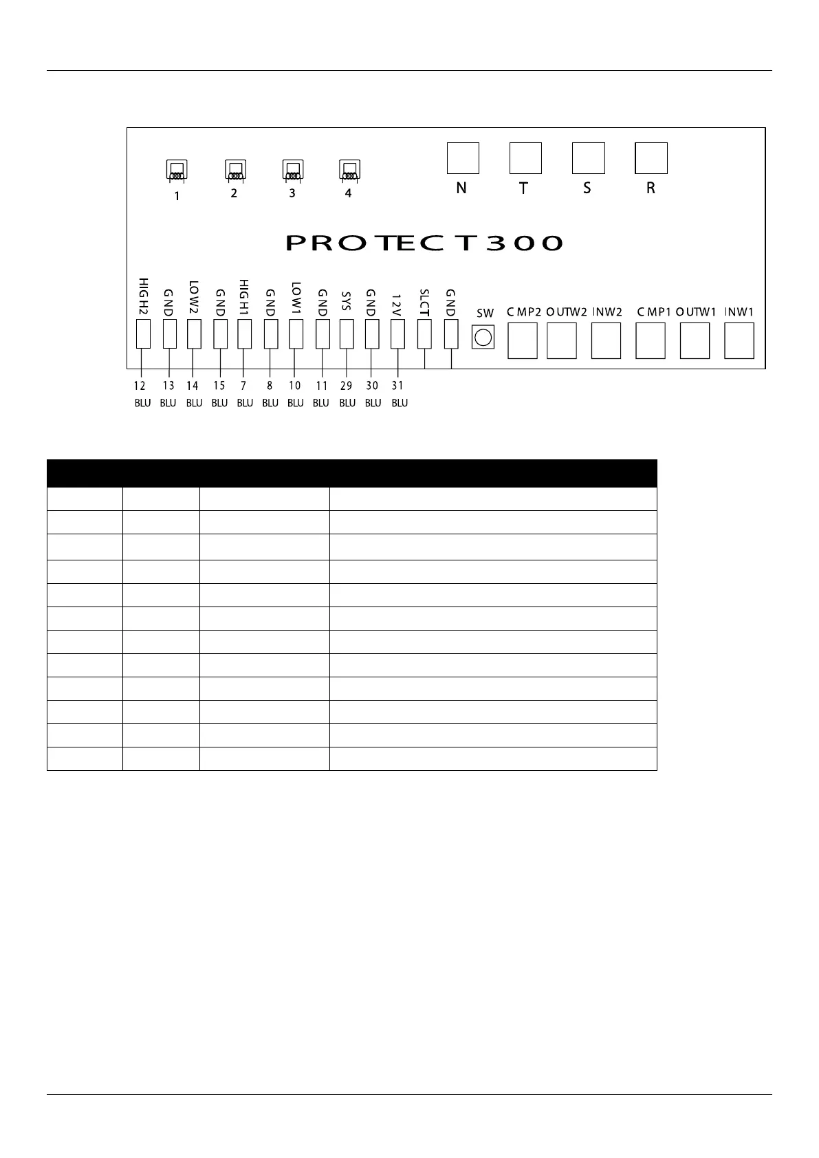
6.3 Connection of protection PCB illustration
CT
Current
Transformer
CT
Current
Transformer
CT
Current
Transformer
CT
Current
Transformer
WIRE NO.
WIRE COLOUR
5
6
7
8
9
10
11
12
13
14
15
16
17
12
7
8
10
13
11
6.4 Connection explanation
Wire No. Port No. Symbol Meaning
12,13 5,6 HIGH H2 GND High pressure protection for system 2 (normal close)
14,15 7,8 LOW 2 GND Low pressure protection for system 2 (normal close)
7,8 9,10 HIGH H2 GND High pressure protection for system 1 (normal close)
10,11 11,12 LOW 1 GND Low pressure protection for system 1 (normal close)
29,30,31 13,14,15 SYS GND 12V Protection signal
SW Current setting (handset)
12 CMP2 Exhausting temp. Of compressor 2
7 OUTW2 Refrigerant temp. After tube (system2) NC
8 INW2 Refrigerant temp. Before tube (system2) NC
13 CMP1 Exhausting temp. Of compressor 1
10 OUTW1 Refrigerant temp. After tube (system 1 (NC)
11 INW1 Refrigerant temp. Before tube (system 1) NC