Maintenance -
continued
Replacing and Cleaning the Air Filter
Stop the engine.1.
Remove the spark plug boot from the spark plug.2.
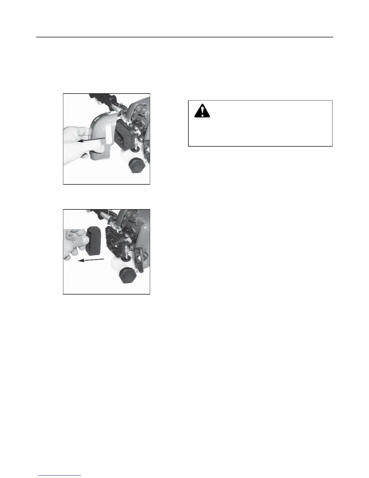
Remove the air cleaner cover (Fig. 12).3.
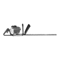
Remove the air fi lter element (Fig. 13).4.
Inspect the element. If the element is distorted or 5.
damaged replace it with a new one.
Clean the air fi lter element by tapping it or by using 6.
compressed air.
Replace the fi lter.7.
Replace the air fi lter cover.8.
Tighten the air fi lter by turning the knob clockwise.9.
Replace the spark plug boot.10.
Spark Plug
This engine uses a NGK BPMR7A with an electrode
gap of 0.63 mm. Use an exact replacement and replace
annually. Tighten to a torque of 12-15 Nm.
Replacing the Cutting Line
See Fig. 14, 15, 16 and 17.
Follow these steps to replace the cutting line
Stop the trimmer.1.
Make sure the trimmer head has fully stopped
rotating. Contact with a rotating trimmer head
could cause personal injury.
WARNING:
Disconnect the spark plug boot.2.
Hold the bump feed and unscrew the spool retainer.3.
Remove the spool retainer by turning anti-clockwise 4.
and remove the spool from the spring head. NOTE:
Keep the spring attached to the spool.
Remove any old line remaining on the spool.5.
Cut two pieces of line, each approximately 5 m long.6.
Insert a piece of line into the slot in the spool.7.
Wind the line around following the direction of the 8.
arrows on the spool, fi lling one half only.
Ensure that about 15 cm of line is not wound. Do 9.
not overfi ll the spool. There should be at least 6
mm space between the wound line and the outside
edge of the spool.
Secure the line end temporarily in the slots on the 10.
upper/bottom fl ange.
Repeat steps 7 -10 for the line, fi lling the other half 11.
of the chamber.
NOTE:12. Ensure that both cutting lines are wound in
the same direction and that the lines do not cross.
Feed each end of the line through opposite metal 13.
eyelets.
Before pulling through completely, ensure line is 14.
released from temporary holding slot.
Push spool fi rmly back in recess and secure the 15.
spool retainer in position.
NOTE:
Check that the bump feed head is locked in place and is
installed correctly back onto the drive shaft.
NOTE:
If insuffi cient line is protruding from the bump feed head,
depress bump feed head and pull in line to manually
advance the line and to check for proper reassembly of
the bump feed head.
Fig. 12
Fig. 13
15