4
TO PREVENT INJURY, ALWAYS DISCONNECT THE AIR SUPPLY
HOSEWHENSERVICINGORDISASSEMBLINGTHETOOL.
When servicing the tool, do not twist or force any parts. Damage may
result from such abuse.
When opening the tool for maintenance, always clean all components
of dirt, grit, or particles. Inspect the tool carefully for broken parts or
excessive wear, and replace if necessary. When ordering parts, be sure
to specify the right part number, and also the tool serial number.
AFTERANYMAINTENANCETOTHETOOL,REMOVEALLCLEATS
BEFORECONNECTINGAIRANDACTUATETHETOOLREPEATEDLY
OVERAPIECEOFWOODORSUBFLOORINGTOINSUREPROPER
OPERATION.
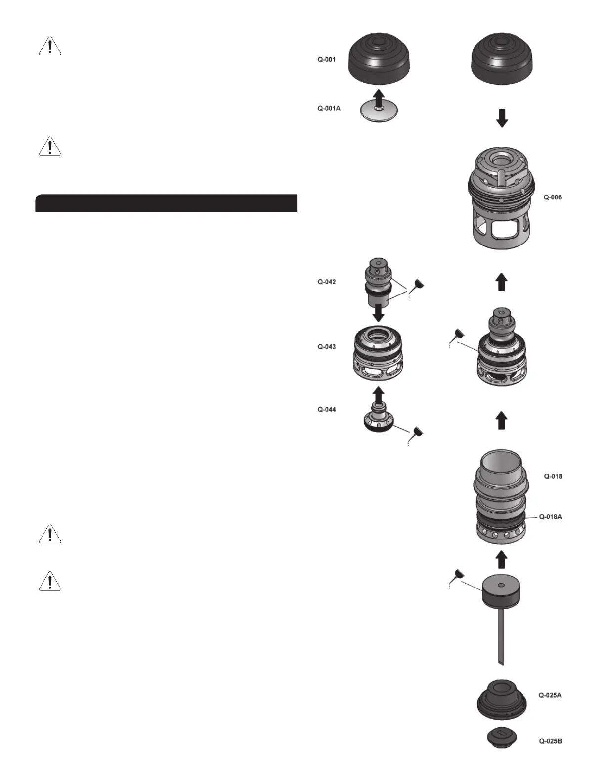
ASSEMBLING THE VALVE
All the components required to drive nails in and reset the tool are
packed in a cartridge assembly which is simply inserted into the tool.
This section describes how to assemble all the components together.
However,itisusuallynotnecessarytocompletelydisassemblethevalve.
Refertonextsection,“CLEANINGTHEVALVE”formoreinformationon
how to open the tool for regular maintenance. The following procedure
assumes that the gate/foot assembly along with the resting block are
already installed. Refer to the “Replacement Parts” document for a
complete list and schematic of the tool.
1. Itisusuallynotrequiredtoseparatetheheaddiskfromtheheadcap.
If necessary, insert the head disk firmly in place into the head cap.
2. Align the inner shape of the head cap with the shape of the head and
snapthecapinplace.Itisusuallynotrequiredtoremovethehead
cap from the head.
3. Check the condition of all rings and seals on the actuator, actuator
cap and main valve.
4. Lightly lubricate actuator as shown and insert it into valve.
5. Lightly lubricate the permanent seal of actuator cap as shown. Do not
lubricatethesmallo-ring(seepartQ-044Conschematic).Insertthe
actuator cap as shown and forcibly snap it into the actuator.
6. Insertthevalvesub-assemblycompletelyintothehead.
7. Checkthattheband-valveisproperlyinstalledontothemaincylinder.
Screwthecylindercompletelyontotheheadbodyandtightenrmly
by hand. Take care not do damage the threads. Pull down the valve to
sit it onto the cylinder.
ALWAYSCHECKTHATTHECYLINDERISCOMPLETELYSCREW-
ONTHE HEAD BEFORE INSERTINGTHE ASSEMBLY INTO THE
TOOL.THECYLINDERWILLLOOSEN-UPWHENTHECARTRIDGE
ISTAKEN-OFFTHETOOL.
ALWAYS PULL DOWN THE VALVE AGAINST THE CYLINDER
BEFOREINSERTINGTHEHEADASSEMBLY.
8.Checkthatthepistonsub-assembly,includingringsanddrivingblade,
is sliding easily into the cylinder . It should offer some resistance, but
ifitmovestooeasily,itmayberequiredtoreplacethepistonwear-
ring.
9. Insert the seal bushing in the lower section of main body and engage
it onto the upper portion of the gate/foot assembly. A flat screwdriver
canhelplocationthesealbushingcorrectly.Usethewoodenhandle
of the hammer to tap the seal bushing completely in place. It is
usuallynotnecessarytopull-outthesealbushingformaintenance.
 Loading...