6
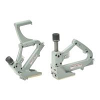
INSTALLING THE SAFETY
You shouldn’t need to remove the safety stop mechanism unless the
element do not swivel or has a broken tip.
a) AssembletogetherpartsQ-061,Q-061A,Q-061CandQ-061D.
b) InserttheshortendoftheconnectingrodQ-061Basshown.
c) PuttwodropsofadhesivesealantontothethreadareaofQ-061C,
near its cylindrical end. Make sure no sealant is retained on the end
or exterior wall.
d) Insert the assembly into the hole in the tool body as shown.
e) TighttogetherwithscrewP-153A,holdingQ-061C.
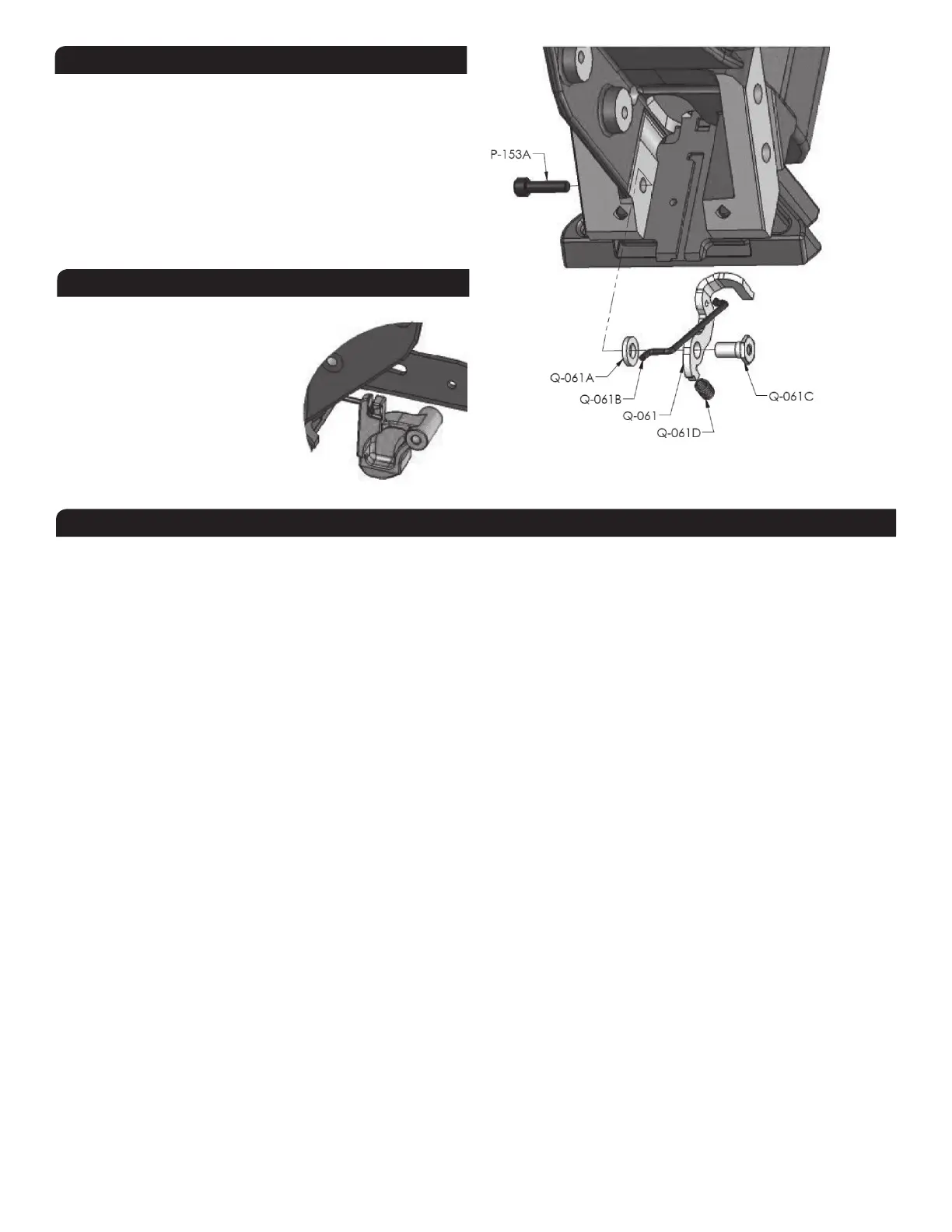
INSTALLING THE BASE ASSEMBLY
The plastic base can be installed or removed without the need of a tool.
a) First, insert connecting stem to the
safety contact.
b) Liftthesafetycontactandfullyslide-
in the base onto the brackets.
c) The safety contact should simply
drop into place. Insert the locking rod
until it snaps. It should engage the
safety contact.
This section will help to diagnose common problems and will give
suggestions on how to solve them.
TO PREVENT INJURY, ALWAYS DISCONNECT THEAIR SUPPLY HOSE
WHENADJUSTING,SERVICINGORDISASSEMBLINGTHETOOL.
(1)FIRST:CHECKTHECOMPRESSEDAIRSUPPLY
Manyofproblemscomefromafaultyorinadequatecompressed
airsupplysystem.Beforeattemptingtorepairthetool,thefollowing
points should be checked:
d) Check the pressure at the output of the compressor; adjust to
80-100psi(5.5-7.0bar)asrequired
e)Check the tank pressure of the compressor & adjust the
start/stop limits
f) Check the air delivery system
g)Usefewer tools simultaneously; donotexceedthe capacityof
the compressor or of the delivery system
h) Drain water from the compressor
(2) SECOND:CHECKFORAIRLEAKS
Atrest,thistoolshouldnothaveanyairleak.Beforeattemptingto
repair the tool and replace parts, check the following:
a)CheckringsQ-006A,Q-016A,Q-042A,Q-043BandQ-043C;
replace if necessary
b) The top edge of main cylinder should be free of dents.
c)Clean&lubricatetheheadassembly;re-assemblethehead
assembly carefully
d) Check interior of head for scratches
(3) TOOLDOESNOTDRIVECLEATS
a) Check that there are cleats in the feeder channel
b) Make sure the feeder clip is engaged behind the cleats
c) Check the front end of the feeder channel for burrs or damages
d) Check the safety mechanism
e) Check if the driver is stuck in down position (see 6 below)
f) Check for obstruction in the cleat ejection area
(4) CLEATSARENOTSETCOMPLETELY
a)First,verifyairsupply(see1above)
b) Clean tool and lubricate tool; particularly the head assembly
c) Increase air pressure when working with harder woods; do
not exceed 110 psi (7.6 bar)
d) Check the driving blade for broken end
e)Check piston wear-ringQ-022A; replace if piston is sliding
to easily
f) ChecksealbushingQ-025B
g) Check the adjustment of the base and ensure the tool is well
seated on the floor while ejecting
(5) TOOLDOESNOTACTIVATE
a) Check the air supply
b) Inspect the head assembly and check all seals;
reassemble carefully
(6) DRIVINGBLADEDOESNOTRETURN
a) Check for jammed cleat or obstruction
b) Check gate/foot and end of feeder channel for damages or
burrs.
c) Check the driving blade d) Inspect the head assembly and
checkallseals;clean&lubricate.
e)Checkband-valve.
f) Check that the bumper and seal bushing are in place.
(7) BROKEN OR WORN DRIVING BLADE Replace the driving blade.
Failure to follow the instructions carefully will result in repeated
breakage of the driving blade.
(8) POORFEEDORTOOLJAMMING
a) Make sure the feeder clip engages behind the cleats
b) Check the gate/foot assembly for damages or wear
c) Check the front end of the feeder channel for burrs or damages
(9) OTHERPROBLEMSContactPorta-Nails:byphone(866)435-8665
byfax(561)241-2830
TROUBLESHOOTING
 Loading...