5
10. With the tool in the upright position, push the bumper in place,
indexed onto the seal bushing and use the wooden handle to seat
the bumper in position.
11. Insert the piston sub-assembly into the main body and engage
the driving blade in the seal bushing opening. Depress the safety
contact to ensure that the driving blade has engaged the gate/foot
assembly guiding channel.
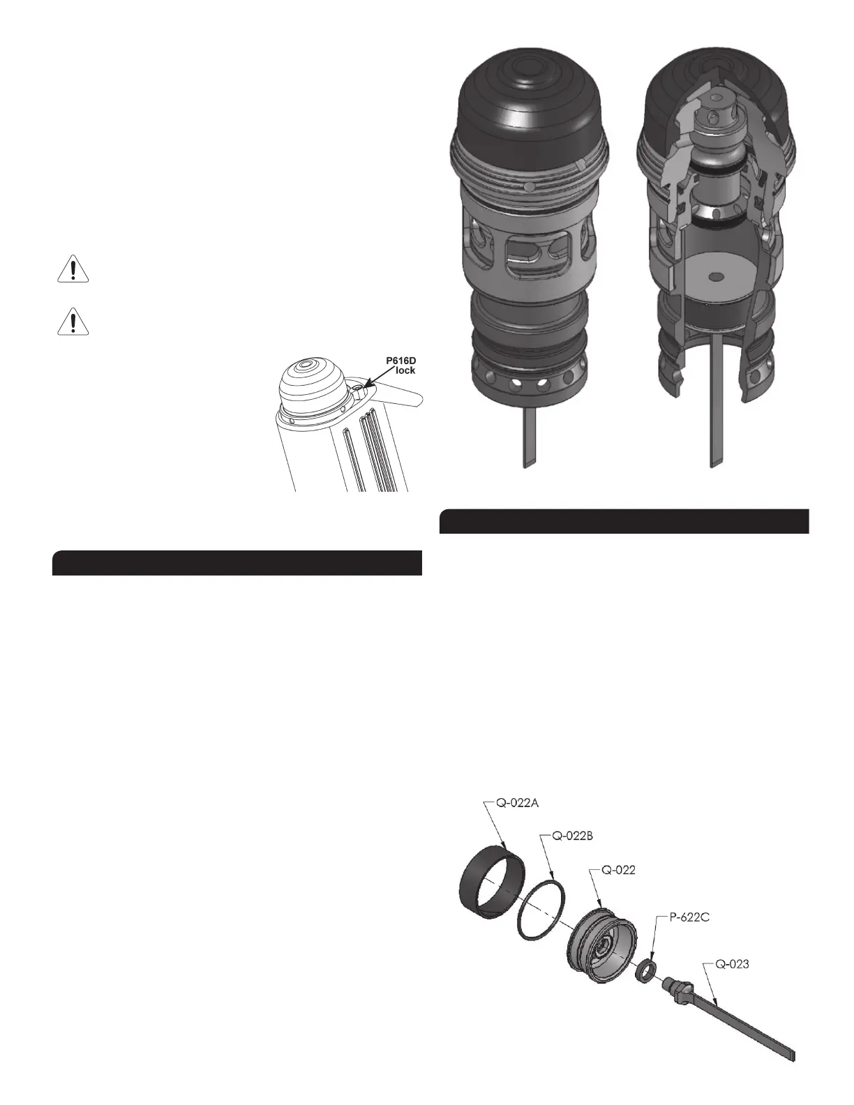
12.LoosenthelockP-616Dandinsertthewholeheadassemblyintothe
main body ; the main cylinder engaging onto the piston assembly.
Screwtheheadassemblycompletely.Takecarenotdodamagethe
threads. Rotate the lock clockwise and tighten with the Allen key
using moderate force.
ITISMOSTIMPORTANTTHATTHEMAINCYLINDERBEFULLY
SCREWED&TIGHTENEDONTOTHEHEADASSEMBLYBEFORE
BEINGINSERTEDINTOTHEMAINBODY.
AFTERREASSEMBLY,ALWAYSACTUATETHETOOLREPEATEDLY
WITHOUT CLEATS AGAINST A PIECE OF WOOD TO INSURE
PROPER OPERATION.
This tool features a head lock to maintain
firmly in place the head assembly during
operation. Before inserting the head
assembly,ensurethattheP-616D lock
is free to swivel and rotate it away from
the head opening. After inserting the
head assembly in place, rotate the lock
and tighten with the Allen key using
moderate force.
To remove the head assembly, simply unscrew the screw ¼ turn and
rotateitcounter-clockwise.
CLEANING THE VALVE
If the tool becomes sluggish or does not set the cleat, it may indicate
excessive dirt, dust, other particles, or even water, in the head assembly,
thereby impeding the cycling of the valve. The first step in troubleshooting
is to clean up the head assembly.
1. Unscrewtheheadassemblyandtakeitoutofthetool.Thelongarm
of a Allen wrench may be inserted into one of hole at the base of head
to help unlock the assembly.
2. Pull-outthepistonassemblyandunscrewthecylinder.Performa
visual inspection of the driving blade, the wearring and the inner
surface of the cylinder. Do not remove the driving blade from the
piston.
3. Pull-out the valve assembly and perform a visual inspection of all
rings. Check that the actuator assembly is sliding easily on valve.
Clean and lubricate lightly. It is usually not necessary to take apart
the actuator assembly.
4. If necessary, actuator cap may be unsnaped from actuator by
inserting the long arm of an Allen wrench through the hole on top
of the actuator and using a hammer with moderate force to get the
parts apart.
5. Clean the inside wall of the head body and lubricate lightly with a
non-detergentoil.Checktheo-rings.Itisgenerallynotnecessaryto
remove the head cap.
Complete 'cartridge' assembly
REPLACING THE DRIVING BLADE
The driving blade is not sold separately, but supplied as a complete
subassembly with the piston. Never remove the driving blade from
the piston.
1. Unscrewtheheadassemblyandtakeitoutofthetool.
2. Pull-outthepistonassemblyfromthecylinder.Removeanydebris
and assess condition of cylinder. If marked or grouged, use a fine
sand paper to smooth out walls. The piston must be allowed to move
without restriction.
3. Insertthepistonsub-assemblyintothemainbodyandengagethe
driving blade in the seal bushing opening. Depress the safety contact
to ensure that the driving blade has engaged the gate/foot assembly
guiding channel.
4. Tighten the cylinder onto the head and follow the procedure to
complete the assembly of the head.
 Loading...