10
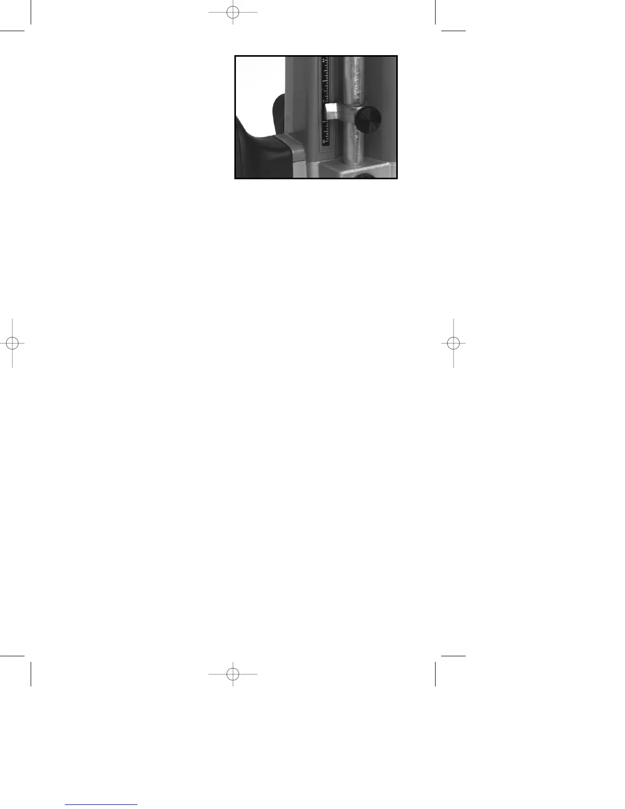
6. Loosen depth rod locking
knob (K) Fig. 9, and raise depth rod
until indicator aligns with the
graduation representing the
desired depth of plunge (The
example in Fig. 13 shows setting
for 1" plunge.) Tighten depth rod
locking knob.
MICRO PLUNGE
ADJUSTMENT
Two separate uses for the micro
plunge adjustment feature are:
1. Hand held plunge router. In this application, set the depth that the router
will plunge. After making a test cut, increase or decrease the depth of plunge
in very precise increments.
2. Shaper mounted in a table. In this application the micro plunge adjusting
knob can be used to make very small and precise adjustments to bit height.
For either application, set the micro adjusting plunge mechanism to the
neutral position by:
1. Moving the plunge locking lever (C) Fig. 8, to the free motion position by
rotating it to the operator’s left as far as it will go (the lever will lock into this
position) and ensuring that a bit is not in the tool.
2. Moving the motor up and down:
A. If the motor will not go all the way down allowing the collet to touch the
work surface, the tool is in the micro plunge adjusting mode. To return
to the neutral position, push the motor down and while maintaining
pressure on the motor, turn the micro plunge adjusting knob (F) Fig. 8
clockwise until the collet nut (D) Fig. 8, touches the surface of the work.
B. If the motor does not rise to the full height the tool is in the shaper table
adjusting mode. To return to the neutral position turn the micro plunge
adjusting knob (F) Fig. 8 counterclockwise until the motor reaches its
maximum height.
Always set the tool to the neutral position after each project is completed and
before storing, so that it is ready to begin the next project.
NOTE: The maximum amount of plunge (maximum amount of motor travel) is
approximately 2
1
/2". The micro adjusting plunge mechanism is in the neutral
position when the motor will move up and down this amount (without a bit
installed).
FOR USE AS HAND HELD ROUTER
1. DISCONNECT TOOL FROM POWER SOURCE.
2. Set the micro plunge adjusting mechanism to the neutral position.
3. Move the plunge locking lever (C) Fig. 8 to the free motion position by
rotating it to the operator’s left until it locks.
4. Raise depth rod (P) Fig. 9 to its highest position.
5. Install bit.
6. Plunge router down by hand until bit is flush with surface of work and hold
firmly.
Fig. 13