11
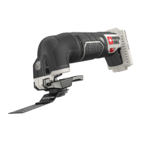
7. Turn micro plunge adjusting knob counterclockwise until resistance is felt
(Fig. 14).
NOTE: This may require 20 or more revolutions.
8. Release the router.
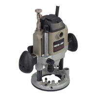
9. Hold micro plunge adjusting knob (F) Fig. 8 while turning micro plunge
adjusting ring (G) Fig. 8 until the “0” lines up with reference mark (A) Fig. 15
on motor housing.
NOTE: For every complete turn of the micro plunge adjusting knob the motor
moves up or down
1
/
8". The graduations on the micro adjusting ring are
marked in
1
/32". To achieve a plunge of
1
/4", turn the micro plunge adjusting
knob 2 complete turns clockwise (
1
/8" +
1
/8" =
1
/4"). To achieve a plunge of
5
/32"
turn the micro plunge adjusting knob 1 complete turn and an additional
quarter turn (one complete turn =
1
/
8" or
4
/
32" and
1
/
4 turn =
1
/
32").
NOTE: The micro plunge adjusting ring will turn with the micro plunge
adjusting knob so that the distance of bit travel is always known.
10. Turn the micro plunge adjusting knob clockwise until the desired depth of
plunge is set.
11. Set the plunge locking lever (C) Fig. 8,to the locked position after the
plunge is adjusted and before the unit is turned “ON”. Move the lever to the
right as far as it will go.
NOTE: The depth rod and depth rod stops may be used in combination with
the micro plunge adjusting mechanism to allow stock removal in steps or for
the various depths that may be required for a particular project.
FOR USE IN A SHAPER TABLE
1. DISCONNECT TOOL FROM POWER SOURCE.
2. Set the micro plunge adjusting mechanism to the neutral position.
3. Move the plunge locking lever (C) Fig. 8 to the free motion position by
rotating it to the left until it locks into position.
4. Remove the sub-base (Fig. 5) and clear dust cover (H) Fig. 8.
5. Move the top switch (I) Fig. 9 to the off position.
6. Lock the handle switch (A) Fig. 8 in the on position.
7. Install the bit.
8. Attach the router to the table according to the table manufacturer’s
instructions.
9. The bit height can be adjusted using the micro plunge adjusting knob. To
raise the bit, turn the micro plunge adjusting knob (F) Fig. 8 clockwise. To
Fig. 14 Fig. 15
A