12
lower the bit, turn the knob counterclockwise.
10. The plunge locking lever (C) Fig. 8 should be set to the locked position
after the bit height is adjusted and before the unit is turned on. Move the lever
to the right as far as it will go.
ADJUSTING PLUNGE LOCKING LEVER
The plunge locking mechanism may be adjusted to compensate for wear, or
to reposition lever (in locked position). To adjust:
1. DISCONNECT TOOL FROM POWER SOURCE.
2. Lock the plunge locking lever, (C) Fig. 8 by moving it to the operator’s
right as far as it will go.
3. Push in on the plunge locking lever (C) Fig. 8.
4. Move the plunge locking lever (C) Fig. 8 to the desired location and allow
it to spring back into position.
Adjust the plunge locking mechanism in the following manner:
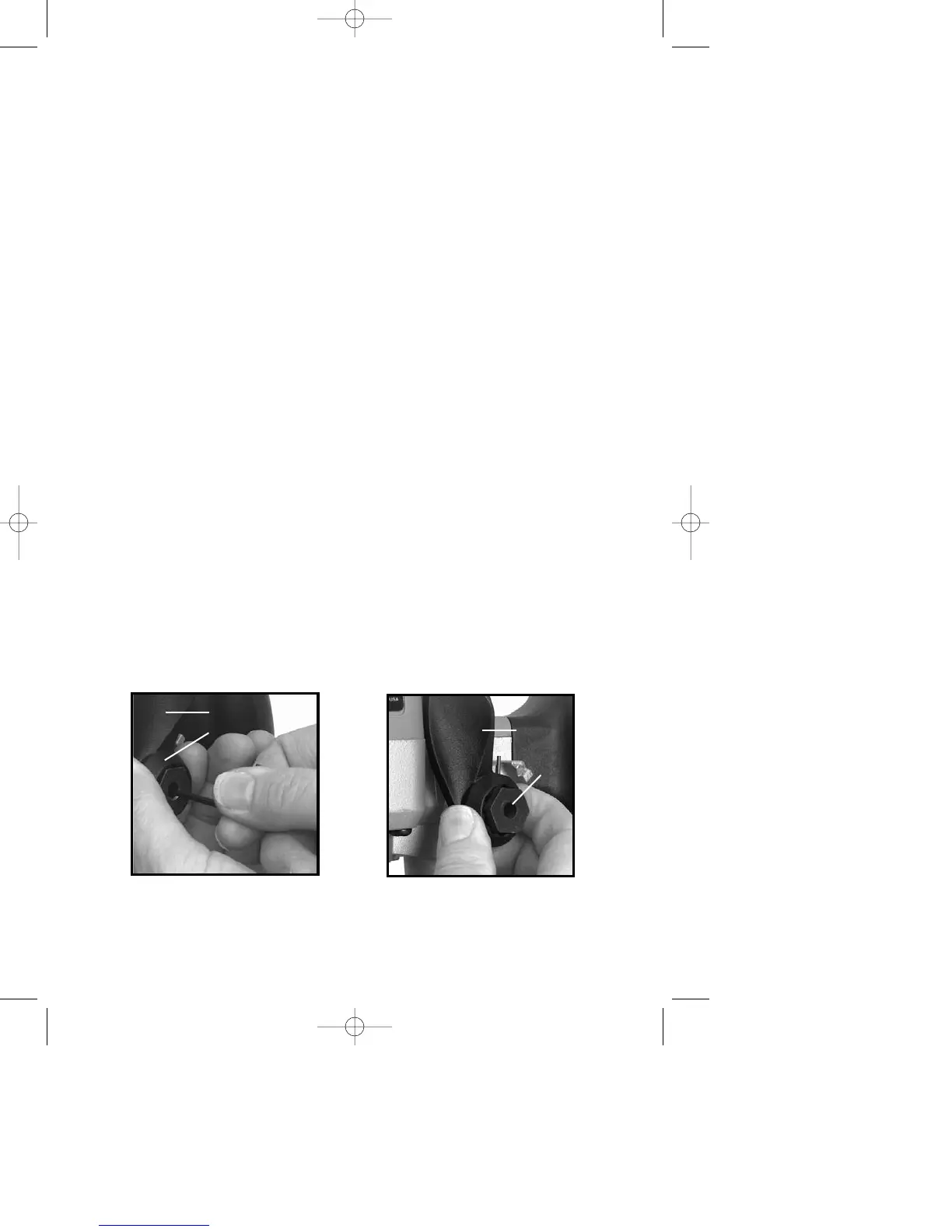
1. Hold plunge locking lever (A) Fig. 16.
2. Insert
1
/
8" allen wrench (not furnished) through center of plunge locking bolt
(B) Fig. 16 into adjustment screw, and turn counterclockwise approximately one
turn.
3. Push in on plunge locking lever (A) Fig. 17 to expose head of plunge
locking bolt (B) Fig. 17.
4. While holding plunge locking lever in (A) Fig. 17, turn plunge locking bolt
(B) Fig. 17 clockwise to turn plunge locking bolt in or counterclockwise to turn
plunge locking bolt out. Turn it one position at a time until proper adjustment
is achieved. Proper adjustment is indicated when plunge locking lever (A)
Figs. 18 and 19 can be locked into the free motion position as shown in Fig.
18, and into the plunge locked position (Fig. 19).
5. Move plunge locking lever (A) Figs. 18 and 19 to the center of those 2
positions. Insert allen wrench through center of plunge locking bolt (B) Fig. 16
into adjustment screw. Turn clockwise to tighten.
TO START AND STOP THE ROUTER
Make sure power circuit voltage is the same as shown on the specification
plate on the router, and that both switches are “OFF”. Connect router to power
source.
Fig. 16
A
B
Fig. 17
A
B