Height Adjuster Model 75301
To use the 75301 Height Adjuster with a router mounted in a table, there needs to be
a hole (or holes) in the table for the Adjuster to reach the router.
IMPORTANT: The instructions below are for some specifi c situations where
holes NEED TO BE DRILLED. Check your table to see if holes are already
provided to allow the Adjuster clearance.
If you are not using a Porter-Cable router table, your router’s sub-base (Fig. 2) can
be used as a template to determine where holes need to be drilled. Use the instruc-
tions below as a general guide on how to attach the Adjuster for a non-Porter-Cable
table.
DISCONNECT ROUTER FROM POWER SOURCE BEFORE
ASSEMBLING THE HEIGHT ADJUSTER.
WHEN USING WITH THE 698 ROUTER TABLE
AND THE 890 SERIES ROUTERS:
1. Make sure router is not attached to the table. Remove the router’s plastic sub-
base (an example of one type used with the 890 router is shown in Fig. 3).
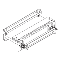
2. Flip the table over with the fence side on top, as in Fig. 4. Then, with the
smooth side of the sub-base against the bottom of the table, line up the
three holes (A) Fig. 3 in the sub-base with the three holes (C) Fig. 4 in the table.
Make sure holes (B) Fig. 3 are on the bottom when the three holes (A) and (C) are
aligned.
3. Use the screws supplied with the table to hold the sub-base in place. Looking
straight down on holes (B) Fig. 3, center punch or mark a spot in the table in the
center of these holes (B).
4.
Before you drill the holes, be sure the table is arranged so nothing
below it will be damaged during drilling.
5. Move the sub-base. At your marks, drill a 7/16" hole. Approximate location of
the holes for the 890 Series is represented by the dotted white circles in Fig. 4.
6. Turn table over and attach router as described in the owner’s manual.
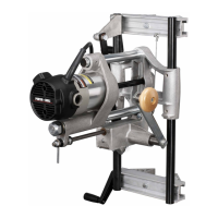
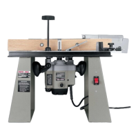
7. Insert Height Adjuster so the index ring (R) rests on the table top (as shown in Fig.
1) and the adjusting arm’s hex opening matches the hex screw in the router.
WHEN USED WITH THE 698 ROUTER TABLE
AND THE 8529 PLUNGE ROUTER:
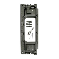
1. Make sure router is not attached to the table. Remove the router’s plastic sub-
base (shown in Fig. 5).
2. Flip the table over with the fence side on top, as in Fig. 4. Then, with the
smooth side of the sub-base against the bottom of the table, line up the
three holes (D) Fig. 5 in the sub-base with the three holes (C) Fig. 4 in the table.
Make sure hole (E) Fig. 5 is on the bottom right when the three holes (D) and (C)
are aligned.
3. Use the screws supplied with the table to hold the sub-base in place. Looking
straight down on hole (E) Fig. 5, center punch or mark a spot in the table in the
center of hole (E).
4.
Before you drill the hole, be sure the table is arranged so nothing
below it will be damaged during drilling.
5. Move the sub-base. At your mark, drill a 7/16" hole. Approximate location of the
hole for the 8529 is represented by the dotted white circle in Fig. 4.
6. Turn table over and attach router as described in the table’s manual.
7. Insert Height Adjuster so the index ring (R) rests on the table top (as shown
in Fig. 1) and the adjusting arm’s hex opening matches the hex screw in the
router.
Fig. 1
Fig. 5
E
D
Fig. 4
C
Router Table Fence Side
A
B
ESPAÑOL en revés / FRANÇAIS sur l’inverse
890 Series
8529
Sub-bases
Fig. 2
Fig. 3
890 SERIES
8529
R
A13729 - 05-18-06
Porter-Cable, 4825 Hwy. 45 North, Jackson TN 38305
www.porter-cable.com (888) 848-5175