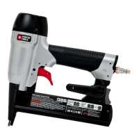
A. Trigger
B. Contact trip
C.
No-mar pad
D. Low nail indicator window
E.
Magazine
F. Magazine Release
G.
Air Inlet
H. Rear exhaust
I.
Adjustable belt hook
J.
Depth adjustment wheel
Actuating tool may result in flying debris,
collation material, or dust which could harm
operator’
s eyes. Operator and others in work
area MUST wear safety glasses with side
shields. These safety glasses must conform to
ANSI Z87.1 requirements (approved glases have
“Z87” printed or stamped on them). It is the
employer’s responsibility to enforce the use of
eye protection equipment by the tool operator
and other people in the work area. (Fig. A)
and other protection during use. Under some
conditions and duration of use, noise from this
pr
oduct may contribute to hearing loss. (Fig. A)
Conden sation
from an air compr
essor can rust and damage the
internal workings of the tool. (Fig. B)
Use air pressure
compatible with ratings on the nameplate of
the tool.
[Not to exceed 120 psi (8.3 bar).] Do not
connect the tool to a compressor rated at over
175 psi. The tool operating pressure must never
exceed 175 psi even in the event of regulator
failure. (Fig.
C)
Only use an air hose that is rated for a
maximum working pressur
e of at least 150 psi
(10.3 bar) or 150% of the maximum system
pressure, whichever is greater. (Fig. D)
Bot
tled compressed gases such as oxygen,
carbon dioxide, nitrogen, hydrogen, propane,
acetylene or air are not for use with pneumatic
tools. Never use combustible gases or any other
reactive gas as a power source for this tool.
Danger of explosion and/or serious personal
injury may result. (Fig. E)
the tool when it is disconnected from the
power supply.
Use hose connectors that shut
off air supply from compressor when the tool is
disconnected. (Fig.
F)
use. Always disconnect tool from air supply
and remove fasteners fr
om magazine before
leaving the area or passing the tool to another
operator. Do not carry tool to another work
area in which changing location involves the
use of scaffoldings, stairs, ladders, and the
like, with air supply connected. Do not make
adjustments, remove magazine, perform
maintenance or clear jammed fasteners while
connected to the air supply. If the contact trip
is adjusted when the tool is connected to the air
supply and nails are loaded, accidental discharge
may occur. (Fig. G)
• Connect tool to air supply before loading
fasteners to prevent an unintentional fastener
discharge during connection. The tool driving
mechanism may cycle when the tool is connected
to the air supply. Do not load fasteners with the
trigger or the contact trip depressed to prevent
unintentional driving.
cause the tool, trigger, or contact trip to
Fig. B
Fig. A
70 psi
4.9 bar
120 psi
8.3 bar
Fig. C
NS150C
Lengths
1/2'' – 1-1/2"
(12.7 mm – 38.1 mm)
Diameters
18 gauge (calibre 18)
Air Inlet 1/4" NPT (1/4 po)
Staple Crown
1/4" (6.4
mm)
Fig. E
Fig. F
Fig. D
Fig. G
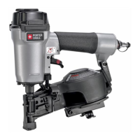
Instruction manual
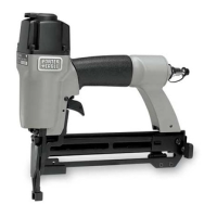
NS150C
CrowN Narrow Stapler
Fig. 1
NS150C
I
H
G
F
J
A
D
C
E
B
DEFINITIONS - SAFETY GUIDELINES
The definitions below describe the level of severity for each
signal wor
d. Please read the manual and pay attention to
these symbols.
Indicates an
imminently hazardous
situation which, if not avoided, will result in death or
serious injury.
In
dicates a potentially hazardous
situation which, if not avoided, could result in death or
serious injury.
Indicates a potentially hazardous
situation which, if not avoided, may result in minor or
moderate injury.
Used without the safety alert symbol
indicates a situation which, if not avoided, may result in
property damage.
SAVE THESE INSTRUCTIONS
I
MPORT
ANT
SAFETY INSTRUCTIONS FOR PNEUMATIC TOOLS
When using any pneumatic tool, all safety precautions, as outlined below, should be followed to avoid the risk of death or serious injury. Read and understand all instructions
before operating the tool.