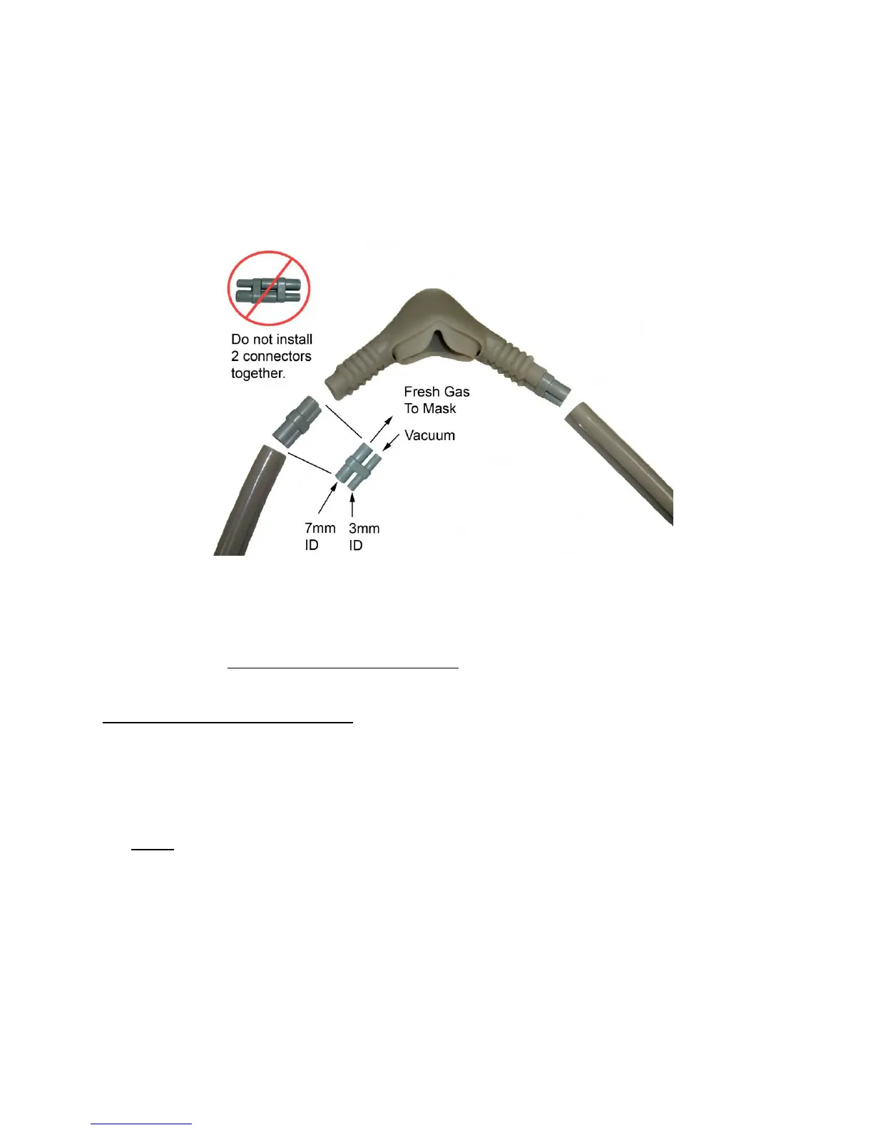
Gas Scavenger Breathing Circuit
Gas scavenger system is used to remove exhaled gases during a dental analgesia conscious
sedation procedure in a dental operatory. The breathing circuit consists of a 22mm 90° elbow
connector, fresh gas / coaxial tubing, a corrugated hose and hood assembly. Attach the nasal
inhaler to the coaxial tubing assembly using the diameter-indexed connectors. Attach one end of
the fresh gas corrugated tubing to the coaxial tubing assembly at the fresh gas “Y” connector and
the other end to the 22mm right angle adapter. Press fit the 22mm right angle adapter onto the
bag tee. Attach the 3L bag to the bottom / downspout of the bag tee. Attach the vacuum hoses
to the vacuum control source (AVS or In-line Vacuum Control Block). Refer to FM-809 for User
Instructions, Assembly, Installation and Cleaning.
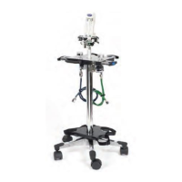
Automatic Vacuum Switch [AVS] (Option)
The AVS is used to control the vacuum flow in the gas scavenger breathing circuit and assure
that the scavenging system is activated as soon as N
2
O / O
2
is turned ON. Adjust the vacuum
flow using the control knob. Vacuum flow is most effective when the ball float is set within the
green bar area. Installation of AVS to Flowmeter: Screw AVS 5000 knurled seal nut down tight
onto flowmeter making sure the rubber washer is inside the seal nut. When tight, the AVS should
not rotate. Then, screw the bag tee seal nut onto the AVS. Bag tee should not rotate.
Connecting AVS to Vacuum Hoses: Attach one end of the vacuum hose to the vacuum hose “Y”
connector and the other end to the MASK port of the AVS. Attach a second vacuum hose to the
VAC port of the AVS and the other end to the vacuum source.
Porter recommends that effective scavenging can be achieved with the ball float in the green bar
area of the acrylic sight glass, however NIOSH publications conclude that higher vacuum flows of
up to 45 L/min are most effective. To meet the NIOSH recommendation of 45 L/min adjust the
ball above the green bar area.
In-line Vacuum Control Kit (Option)
The kit includes a vacuum control block with sight glass, vacuum tube holder, adapter “T” and
straight fitting. The vacuum control block can be inserted directly into the High Volume
Evacuation (HVE) line or may be placed “in-line” by cutting the vacuum hose and attaching the
cut ends of the tubing to both ends of the vacuum control block. Adjust the vacuum flow using
the control knob. Vacuum flow is most effective when the ball float is set within the green bar
area. Refer to FM-809 for User Instructions, Assembly, Installation and Cleaning.
5061 Connector Installation