Page 9
FIGURE E
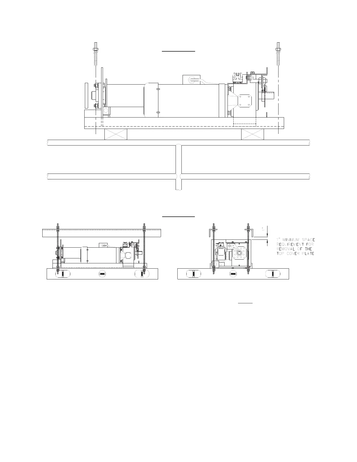
Threaded rod is utilized to ensure each hoist unit is installed level! Installing the unit
level ensures proper cable wind on the hoist drum. After the unit is secured in place as
shown in Figure F, place a level across the lower two (2) angles that comprise the
hoist frame support. Adjust the hex nuts accordingly to level the unit. Do not use the
level on the top cover. The top cover plate may be slightly distorted, giving an
inaccurate reading. Be sure to check for levelness in each direction, utilizing the two
(2) angles of the frame weldment as a base.
A one-inch (1”) space between the top cover of the hoist unit and the overhead
structure is required to provide wiring access by the electrician (again, refer to Figure
F).
Repeat the sequence in Step 5 for the second hoist unit. Note: all threaded rods
require a double nut connection, as detailed in Figure F.
FIGURE F