Page 10
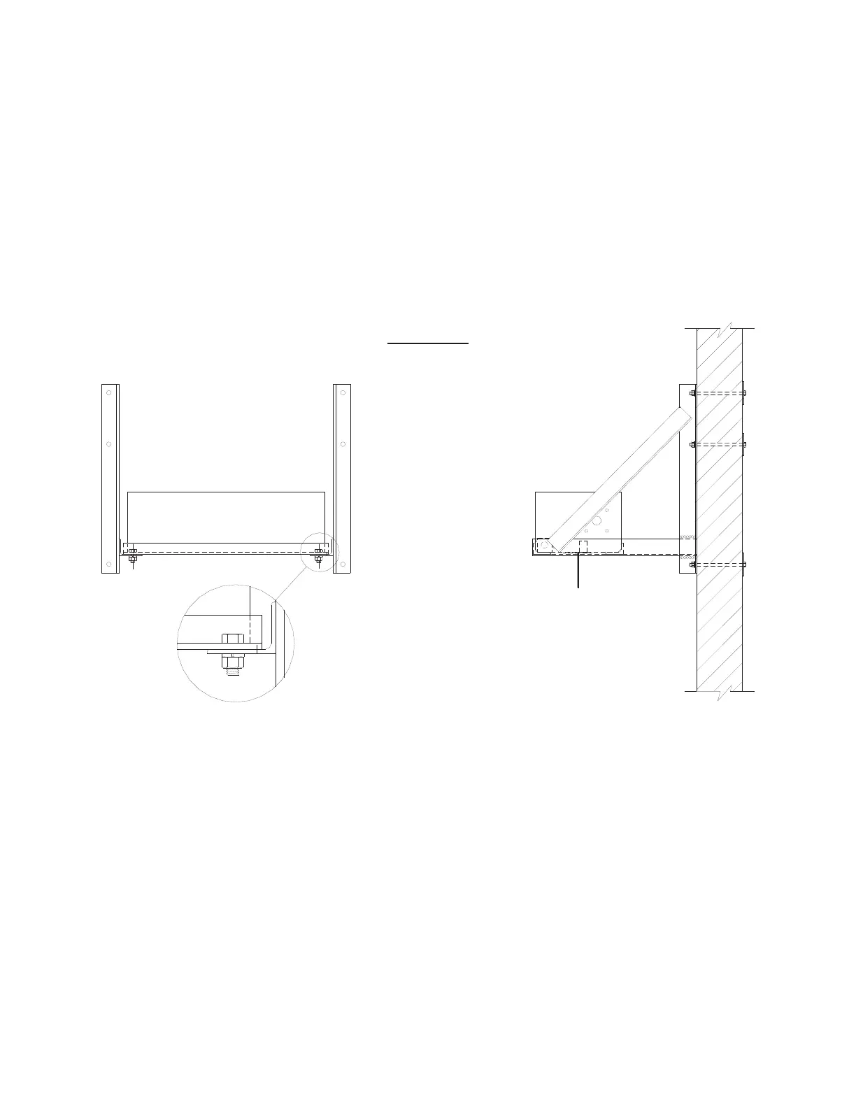
FIGURE G
6. ATTACHMENT OF WALL MOUNTED HOISTS
(Go to Step 7 if units are overhead supported.) With the wall brackets in place as
described in Step 4, the units need to be located as shown in Figure G on top of the
horizontal angle flange of the wall brackets. Refer to Step 5 for hoisting the units in
place. Secure in place with four (4) 1/2” x 1-1/2” long machine bolts with lockwashers
and nuts (see Figure G).
7. UPPER LIMIT ACTUATOR SETTING
The upper limit switch of each hoist unit is actuated by the load bar pushing up the
actuator bar, in turn, activating the limit switch. To install the upper limit actuator bar,
unfasten the full thread bolt from the top of the actuator bar. Apply a small amount of
grease to the top 4” of the bar. Slide the actuator bar through the tube located on the
end plate (between the drum and limit switch). Place the “whisker” spring of the limit
switch through the opening of the top portion of the actuator bar (see Section A-A).
Replace the full thread bolt, making sure the bolt goes through both walls of the
actuator bar. It is imperative the jamb nut be set tight against the bar to keep the bolt
in place. Repeat for the second mat hoist. See Figure H for illustration.