Page 20
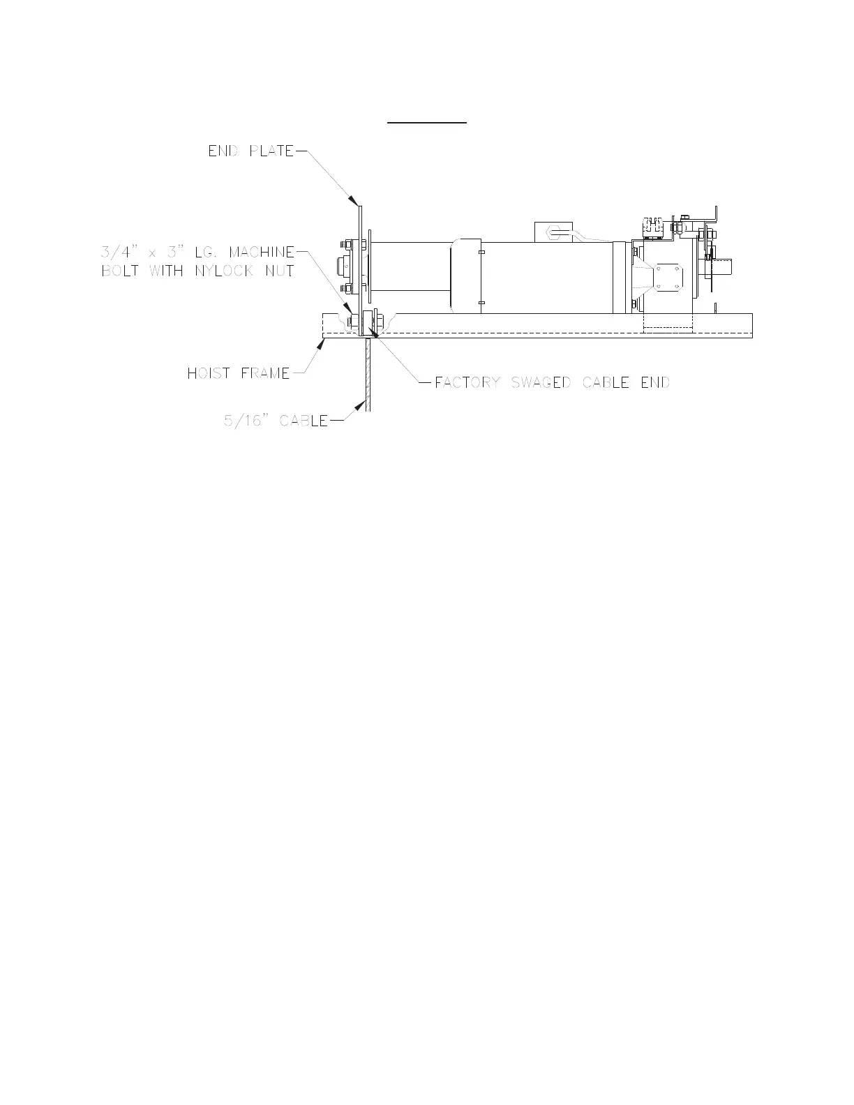
FIGURE N
14. INITIAL HOISTING OF THE LOAD BAR
First, check all hardware connections to ensure they are tight. Re-check clamp or
pulley connection at load bar and verify Grade 8 bolts and nylock nuts were used.
Remember that the grade of bolt cannot be substituted!
Now, raise load bar to approximately 3’-0” above finished floor by turning the (UP) key
to the “UP” position. You are now ready to level the load bar and set the “lower” limit
switches.
15. SETTING THE LOWER LIMITS
Each hoist has a lower limit switch located on the underside of the frame weldment
(see Figure O). With the center section of the load bar elevated 3’-3” off the floor,
move the limit switch assembly on the adjustment rod until the “whisker” arm engages
the hoist cable and the switch opens (“clicks”). At this point, the hoist should not lower
when the key switch is actuated. Make certain there is a minimum of three (3) wraps
of cable on the drum at the lower limit setting.
Repeat the sequence for the second hoist. If the load bar is initially out of level, it can
be leveled by adjusting the two (2) lower limit switches. Do not raise the load bar all
the way up until the bar is level.