Page 16
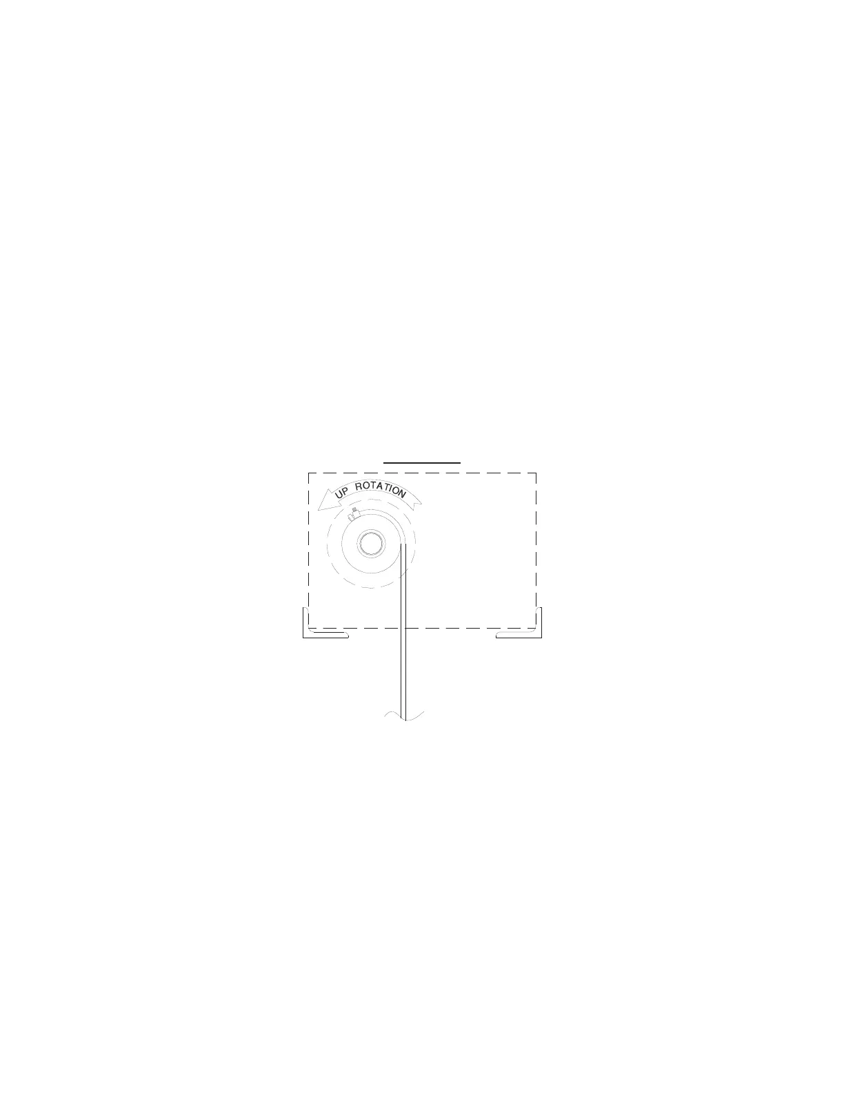
FIGURE L
10. OPERATIONAL CHECK PROCEDURE
This procedure ensures the Mat Mover
®
system has been wired properly. Also, refer to
Step 11 for a cross-check of Mat Mover
®
functions with the corresponding control
panel light, if necessary.
10.1 Ensure motor overload relays in the control panel are in the “ON” position.
10.2 Turn Mat Mover
®
control panel switch to the “ON” position.
10.3 Turn power “ON” at power source.
10.4 Operate unit briefly in the “UP” direction to check for proper phasing (see
phasing note). Disregard the keyswitch faceplate for direction of travel identification
at this time. Instead, observe the cable drum rotation to identify the travel direction.
See Figure L for travel direction identification.
10.5 During the check procedure, all references made to actuating a limit switch
are to be done manually to ensure the unit is phased properly, preventing all limits
from being put in an override situation and causing personal injury and/or
structural damage. Manually actuate all limits with a broom stick or other similar
extension, taking precaution that hands, limbs, hair, and clothing are not near the
rotating drums.
With cable drum turning in the “UP” direction, actuate either the left or right “UP”
limit switch. If cable drum stops, the vertical direction of travel is phased properly
(“IN PHASE”). If cable drum continues to operate while the “UP” limit switch is
actuated, the vertical direction of travel is not phased correctly.
If vertical travel is “IN PHASE,” proceed to Step 10.7. If vertical travel is not phased
correctly, proceed to the next step.