SERVICE MANUAL
Page 14
Service manual Jetstream Mk3 - V. 1.0 - 11-02-08 Approved by: JN
JETSTREAM Mk3
Step Parts Tools/Instructions Replace Picture
7
2857
2787
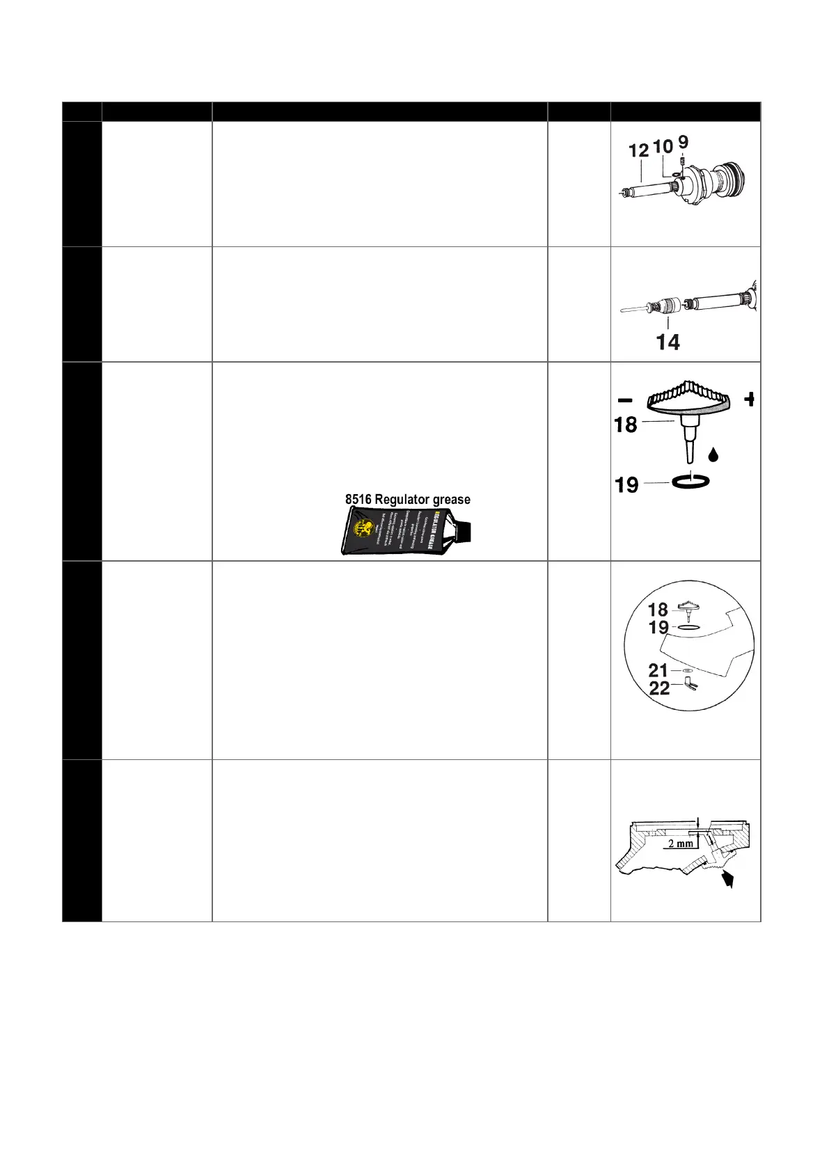
Install the rubber plate (10). Screw in
the stop screw (9). Tighten the stop screw to a
point where you can still turn the valve tube (12).
8
2786
Screw the servo valve (14 ) on to valve tube
(12).Tighten up. Be careful not to bend the valve
needle.
9
2711
1851 SWITCH (Only if the switch is damaged)
Fit in o-ring (19) and lubricate it.
Fit in the switch with the narrow part against
the - minus sign on the second stage valve. See
Picture.
10
2711
1851
2794
2712
Install the locking washer (21) on the switch (18).
Press it on a drift. Tighten the locking washer so
that there is sufficient resistance when
setting the switch.
Fix the diaphragm cam (22) upon the switch
(18). Set switch at - (minus), press the
diaphragm cam into correct position per the
diagram.
11
The distance from the top of the diaphragm
cam to the housing should be 2 mm, concerns
diaphragm of silicone rubber, see diagram.
Carefully push diaphragm cam into the right
position. Note the cam should be pushed slowly
on to the switch so that the switch is not moved.