G1002-C Quick Installation Guide
Positron Access Solutions 8 Document 180-0219-001 R01
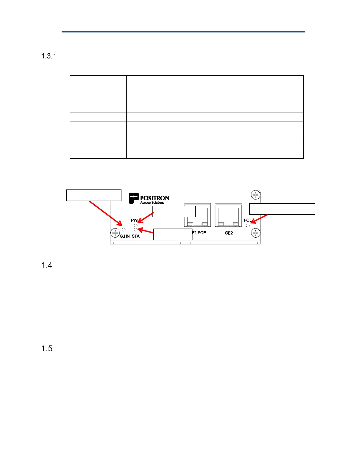
G1002-C+ LED Definition
The G1002-C+ status LEDs are defined in the following table:
ON indicates G.hn link up
OFF indicates G.hn link down
BLINKING indicates G.hn link speed less than 40 Mbps
Table 2: G1002-C+ LED Definition
Figure 6: G1002-C+ LED definition
G1002-C / G1002-C+ Gigabit Ethernet Ports
The G1002-C and G1002-C+ incorporate two (2) RJ-45 Gigabit Ethernet ports.
Please note that port GE1 can be configured in VLAN Trunk mode (via the GAM)
if required for your application.
The GE1 port of the G1002-C+ supports Power Over Ethernet to power an external
device. When locally powered, the G1002-C+ can provide up to 30W of power as
per the IEEE 802.3at standard.
Physical Mounting of the G1002-C / G1002-C+
The G1002-C and G1002-C+ share the same base enclosure and have the same
mounting options. You can optionally install (mount) the enclosure on a wall or flat
surface as follows:
1. Select a proper mounting location where you can securely install mounting
screws (not supplied).