Do you have a question about the Potterton Titanium 28 and is the answer not in the manual?
Ensures correct equipment, competent installation/servicing, and compliance with Building Regulations for customer benefit.
Building Regulations require notification of appliance installation to Local Authority Building Control or via Self-Certification Schemes.
The company supports the Benchmark initiative to improve installation and commissioning standards for safety and efficiency.
Appliance must be installed per manufacturer instructions and current regulations, by a competent person.
A Gas Safe registered engineer with relevant ACS modules is considered competent.
Boiler is for GB/IE installation only, following relevant standards and codes of practice for safety and performance.
Advice on coordinating movements, planning ahead, ensuring clear routes, and using PPE for safe boiler handling.
Guidance on proper lifting techniques, keeping the back straight, bending knees, and avoiding twists.
Emphasizes assessing installation risks and stopping if injury is felt, seeking assistance if in doubt.
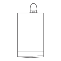
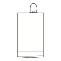
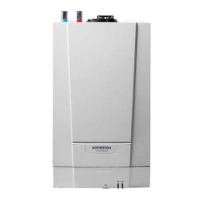
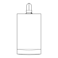
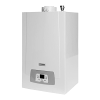
Overview of the Potterton Titanium condensing combination boiler and its model outputs.
Lists the items included with the boiler unit upon purchase.
Diagram and key identifying all major components and their locations within the boiler.
Explains how the boiler functions for central heating, including pump overrun and anti-cycling.
Details the priority given to DHW, how the system activates, and temperature control.
Describes the boiler's integral frost protection feature activated below 5°C.
Comprehensive technical data for all Titanium models, including performance, electrical, and physical specifications.
Table detailing the boiler's dimensions and required installation clearances.
Diagram showing the layout and sizes of all pipe connections on the boiler.
Information regarding water byelaws and approvals relevant to boiler installations.
Guidance on system type, water treatment, flushing, and inhibitor use for central heating circuits.
Explanation of the DHW plate heat exchanger's role as an automatic bypass.
Step-by-step instructions for filling the central heating system to the correct pressure.
Details on the pressure relief valve setting, discharge pipe requirements, and safety.
Guidelines for DHW circuits, water regulations, pressure limits, and potential issues in hard water areas.
Advice on selecting suitable shower controls for use with the appliance.
Criteria for choosing a suitable installation location and securely mounting the boiler.
Specifies minimum required clearances around the boiler for safe operation and maintenance.
Requirements for gas supply connection, including pipework size and standards.
Details on electrical supply voltage, fusing, and the need for proper isolation.
Specific electrical zoning and installation rules for bathrooms.
Essential instructions for correctly installing the condensate discharge pipe to prevent freezing and lockout.
Diagrams and descriptions for various condensate drain termination options, including soakaways.
Information on optional accessories like condensate pumps and trace heating elements for drain pipes.
Rules for positioning flue terminals to prevent nuisance and ensure safe combustion product dispersal.
Details on standard horizontal flue kits, fittings, engagement, and length calculations.
Information on vertical and twin flue systems, including equivalent lengths and support methods.
A list of available flue accessories with their respective part numbers and sizes.
Instructions for fitting the adaptor to connect a twin flue system to the boiler.
Guidance on correctly engaging and securing twin flue ducts and joints.
Specific steps for installing flue terminals on pitched and flat roofs.
Specifies the maximum permissible equivalent flue lengths for horizontal and concentric systems.
Instructions for installing a terminal guard if required by regulations.
Details the components included in the plume displacement kit for managing flue emissions.
Explains how to use graphs and calculations to determine maximum flue lengths with extensions and bends.
Step-by-step instructions for installing the plume displacement kit, including wall penetration and terminal positioning.
Further guidance on routing, positioning, and securing plume displacement kit components for optimal performance.
Steps for unpacking the boiler and correctly mounting the wall plate.
Instructions for flushing the central heating system prior to boiler connection.
Detailed guide on connecting the filling loop for system pressurisation and refilling.
Instructions for lifting, mounting the boiler, and connecting pipes to the wall plate.
Guidance on routing and connecting the discharge pipe for the pressure relief valve.
Instructions for connecting the condensate drain pipe to the household drainage system.
Step-by-step guide for installing the standard horizontal flue kit, including measurements and cutting.
Instructions for fitting inner flue support brackets and concentric vertical flue extensions.
Steps for connecting external controls like thermostats and timers to the boiler.
Essential electrical checks required before commissioning the boiler.
Procedure for initial boiler commissioning, including system checks, gas checks, and control setup.
Mandatory procedure for checking and adjusting combustion ratios.
How to check operational gas inlet pressure and measure the gas rate for correct boiler operation.
Instructions for programming the built-in timer for central heating schedules.
Steps for demonstrating boiler operation to the user and completing final documentation.
Guidelines and safety checks for performing annual maintenance on the boiler.
Detailed inspection procedures for key components like the burner, electrodes, and heat exchanger.
Procedures for replacing the igniter, spark electrode, and sensing electrode.
Instructions for replacing the fan assembly, venturi, and injector components.
Procedures for replacing the burner unit and internal insulation.
Procedure for replacing flue/heat exchanger, CH/DHW temperature sensors, water pressure sensor, and safety thermostat.
Instructions for replacing the pump head, complete pump, and automatic air vent.
Procedures for replacing the pressure gauge, Hall Effect sensor, and pressure relief valve.
Instructions for replacing the plate heat exchanger and the diverter valve unit.
Procedures for replacing the boiler's printed circuit board (PCB) and selector switch.
Steps for replacing the gas valve and expansion vessel, including critical adjustments.
Detailed steps for checking and adjusting the gas valve's CO2 levels using a combustion analyser.
A comprehensive wiring diagram illustrating the electrical connections of the boiler components.
A list of major boiler components with key numbers and manufacturer part numbers.
Basic troubleshooting steps, including supply checks and initial diagnostics before proceeding.
A guide to understanding and interpreting the error codes displayed by the boiler's facia.
A step-by-step flowchart to diagnose and resolve faults during central heating operation.
A step-by-step flowchart to diagnose and resolve faults during DHW operation.
Troubleshooting steps for power, pump, PCB, water pressure, and fan related faults.
Troubleshooting steps for sensor faults, gas valve issues, and ignition problems.
Troubleshooting steps for gas supply, overheat thermostat, motor valve, and heat exchanger issues.
A blank section for users to record important notes or observations.
Checklist for verifying installation of controls, system flushing, and inhibitor treatment.
Sections to record gas rate, pressures, temperatures, and combustion analysis results.
Confirmation of compliance with regulations and handover of documentation.
Forms to record details of annual servicing, including engineer, gas safe number, and combustion readings.
| Output | 28 kW |
|---|---|
| Fuel Type | Natural Gas |
| Mounting | Wall-mounted |
| ERP Rating | A |
| Central Heating Flow Temperature | 30 - 80 °C |
| Type | Condensing Boiler |
| Boiler Type | Combi |
| Water Pressure | 1-3 bar |