INSTALLATION AND CONNECTION
3.2. Connections for Profibus Board
3.2.1. Description of Connectors and Leds
In the Profibus board there are two connectors used to connect the
board to the SD700 drive. The other connector (9 Pin D-SUB / F) is
used for the connection to the Profibus network. On the other hand,
the leds supply information about the input power of the board,
network detection and communication status.
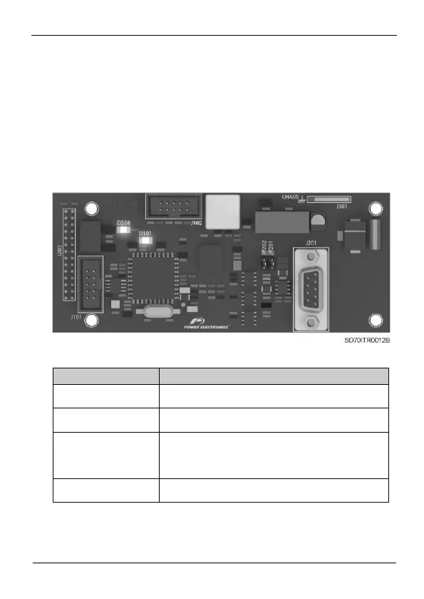
Figure 3.2 Location of connectors and leds on Profibus board
Connector SUB-D 9 pins to connect the signals of the
Profibus network.
Connector available to provide the connection of the board
to the Earth system.
To connect the ending resistors of the network. If it is not
necessary to enable the ending resistor of the network, the
jumper will be not connected. Otherwise, the jumper will be
connected and so these resistors will be enabled.
Green. “ON” led. If it is lit indicates that the board is power
supplied.