INSTALLATION AND CONNECTION
Red. It provides information depending on the number of
blinking.
Profibus Configuration error
Profibus not yet configured
Device in data exchange mode
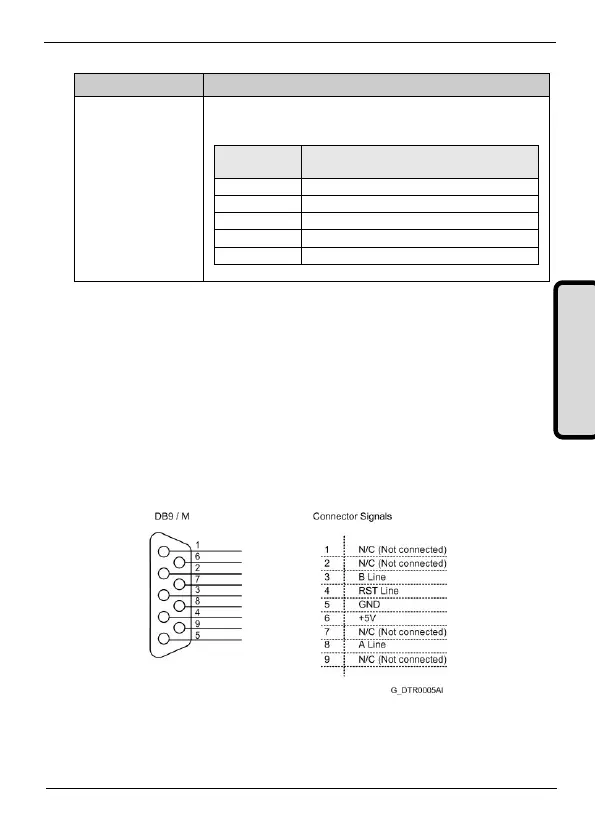
3.2.2. Profibus Connections
For Profibus connection, a standard connector SUB-D 9 pins is used
according to the definition of the standard EN 50170. The wiring for
the connector of nine pins is shown in the attached figure.
If additionally, more information is required, refer to “Installation
Guide of PROFIBUS DP/FMS" of the Profibus users group, where
you can find more detailed information about the connection.
Figure 3.3 Connections of the connector SUB-D 9 pins